Automatic system for drilling fluid water analysis and detection
An automation system and drilling fluid technology, applied in the direction of chemical analysis by titration method, transmission of sensing components by electric/magnetic devices, etc., can solve the problems of manpower consumption and low degree of automation, and achieve rapid flushing and rapid titration detection Effect
- Summary
- Abstract
- Description
- Claims
- Application Information
AI Technical Summary
Problems solved by technology
Method used
Image

Examples
Embodiment 1
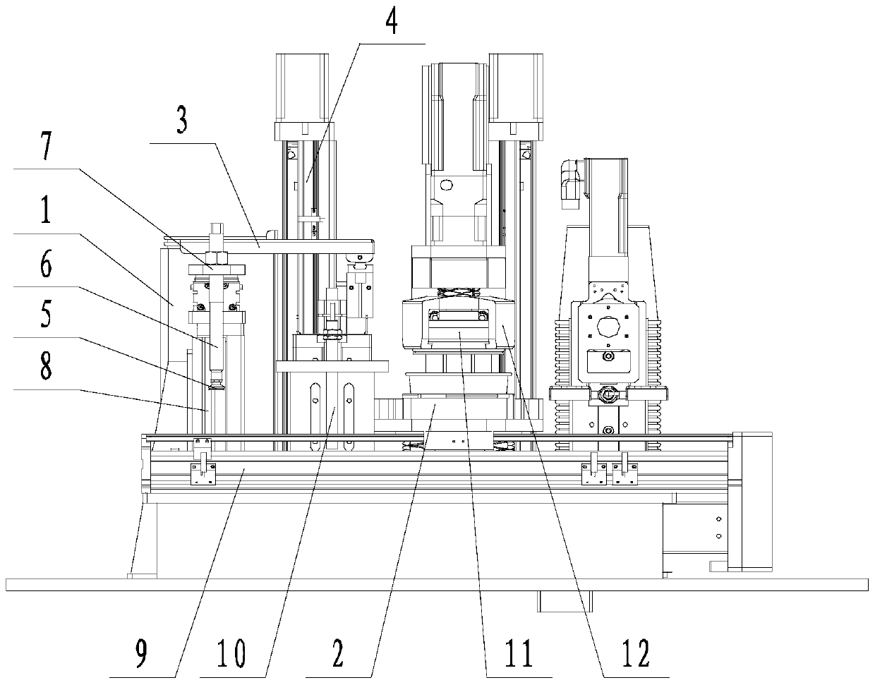
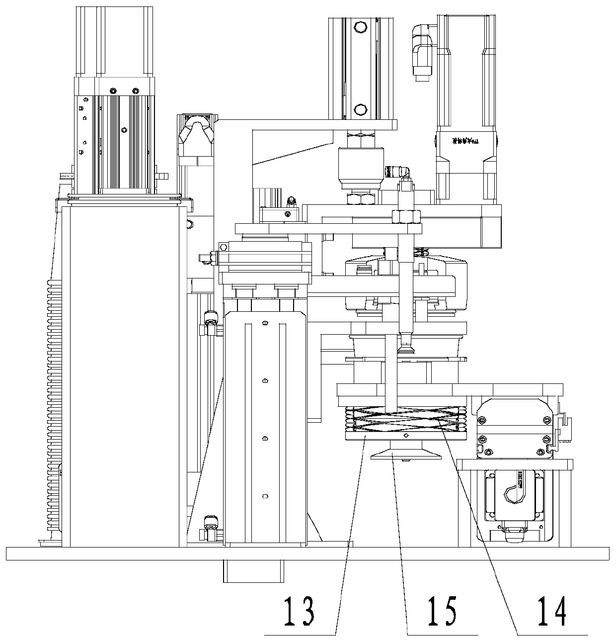
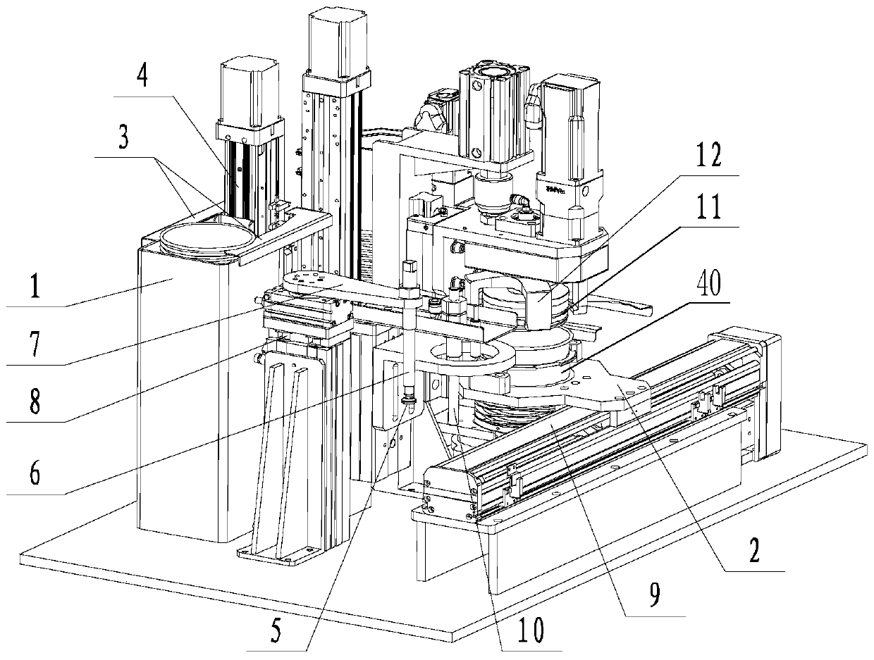
[0042] like Figure 1 to Figure 6 The shown automatic system for drilling fluid water analysis and detection includes an inner cup taking component, an inner cup recovery component, and a filtrate detection component; the inner cup taking component includes a forward position 1 for the inner cups to overlap , a cup taking mechanism that takes out the inner cups one by one from the normal position 1, a clamping device 2 for clamping the inner cups taken out by the cup taking mechanism, a conveying mechanism for moving the clamping device 2, and a conveying mechanism located at the conveying mechanism The grouting device 10 on the path, the pressurized plug 11 located on the delivery path of the conveying mechanism; the inner cup recovery assembly includes an inner cup clamp 16 for taking over the inner cup from the clamping device 2, and is used to drive the inner cup The first rotating mechanism 17 for the cup clamp 16 to rotate along the horizontal axis, the second rotating m...
Embodiment 2
[0044] like Figure 1 to Figure 6 In the shown automated system for drilling fluid water analysis and testing, on the basis of Example 1, the upright and unloading station 1 is a box structure surrounded by three plates. It also includes an inner cup pressing assembly facing the normal placing station 1, and the inner cup pressing assembly is used to press the lower inner cup. The inner cup pressing and holding assembly includes two openable and closing pressing plates 3, and the inner cup pressing and holding assembly is driven by the first lifting mechanism 4 to lift. The cup taking mechanism includes a suction cup 5 with an opening facing downwards, an air suction pipe 6 connected to the suction cup 5, a swing arm 7 for driving the suction pipe 6 to rotate, and a second lifting mechanism 8 for driving the swing arm 7 up and down. The conveying mechanism is a guide rail 9 , and the clamping device 2 can move on the guide rail 9 . It also includes a grouting device 10 , and...
Embodiment 3
[0048] like Figure 1 to Figure 6 In the shown automation system for drilling fluid water analysis and testing, on the basis of any of the above embodiments, the second rotating mechanism 18 drives the inner cup fixture 16, the first rotating mechanism 17, and the lifting assembly 20 to rotate synchronously. The second rotating mechanism 18 drives the mounting seat 19 to rotate, the connecting plate 21 is arranged on the mounting seat 19, the first rotating mechanism 17 is installed on the connecting plate 21, the output end of the first rotating mechanism 17 is connected with the inner cup clamp 16 connected. The lifting assembly 20 is used to drive the connecting plate 21 to lift on the mounting base 19 . A water tank 22 is also included, and the second rotating mechanism 18 can drive the inner cup clamp 16 to pass above the water tank 22 . It also includes an undercut station 23 , which is used for undercutting and overlapping the inner cups; the second rotating mechanism...
PUM
 Abstract
Description
Claims
Application Information
 - R&D
- Intellectual Property
- Life Sciences
- Materials
- Tech Scout
- Unparalleled Data Quality
- Higher Quality Content
- 60% Fewer Hallucinations
Browse by: Latest US Patents, China's latest patents, Technical Efficacy Thesaurus, Application Domain, Technology Topic, Popular Technical Reports.
© 2025 PatSnap. All rights reserved.Legal|Privacy policy|Modern Slavery Act Transparency Statement|Sitemap|About US| Contact US: help@patsnap.com