
hydraulic camshaft adjuster

A camshaft adjuster and hydraulic technology, which is applied in the direction of machines/engines, valve devices, mechanical equipment, etc., can solve the leaking of the hydraulic camshaft adjuster, the difficulty of adjusting the hydraulic camshaft adjuster, and the limitation of functional adjustment speed, etc. problems, achieve high adjustment force and adjustment torque, improve efficiency, and increase friction

Active Publication Date: 2021-11-30
SCHAEFFLER TECH AG & CO KG
View PDF9 Cites 0 Cited by
  • Summary
  • Abstract
  • Description
  • Claims
  • Application Information

AI Technical Summary

Problems solved by technology

However, this solution has the disadvantage that the seals cause additional friction, which makes the adjustment of the hydraulic camshaft adjuster difficult, and that wear can occur during the use of the hydraulic camshaft adjuster, which leads to hydraulic camshaft adjustment. Leakage of the device, which may limit the functionality and especially the adjustment speed

Method used


Image

  • hydraulic camshaft adjuster
  • hydraulic camshaft adjuster
  • hydraulic camshaft adjuster

Examples


Embodiment Construction

[0027] specific implementation plan

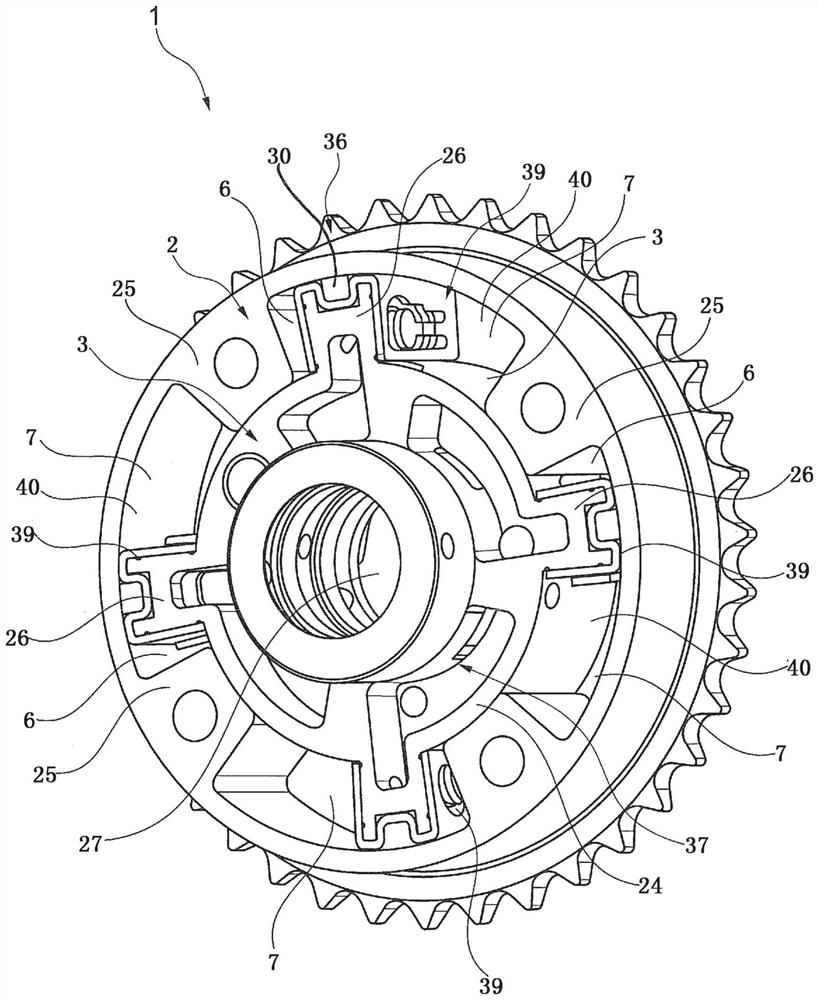
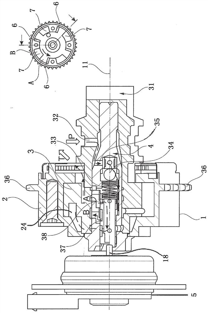
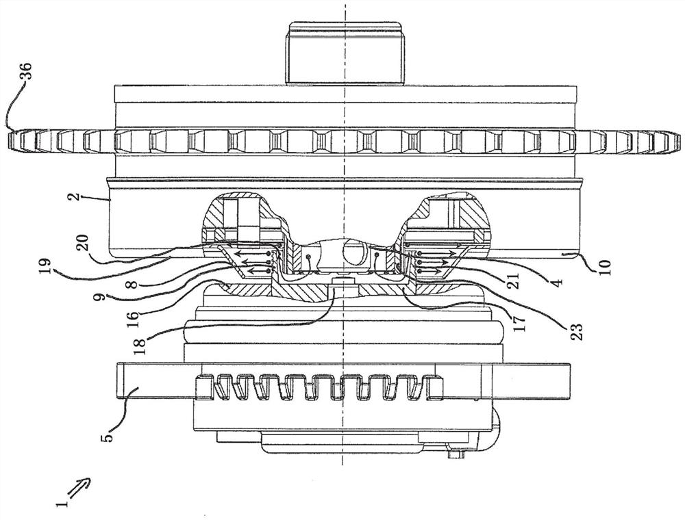
[0028] figure 1 A hydraulic camshaft adjuster 1 for adjusting the valve timing of an internal combustion engine is shown. The hydraulic camshaft adjuster 1 has a stator 2 and a rotor 3 . In this case, rotor 3 and stator 2 are arranged centrally about a common central axis 11 . The rotor 3 has a central opening 27 in which is arranged a central valve 4 for hydraulically controlling the working chambers 6 , 7 of the hydraulic camshaft adjuster 1 . Channels 37 , 38 are formed in stator 2 and / or rotor 3 for conveying or discharging hydraulic oil 12 into working chambers 6 , 7 . An annular space 40 is formed between the stator 2 and the rotor 3 . The stator 2 has inwardly protruding webs 25 in the radial direction, which delimit the individual pressure chambers of the hydraulic camshaft adjuster 1 . Outwardly protruding vanes 26 are formed on the rotor 3 in the radial direction and divide the individual pressure chambers into a first worki...


PUM


Abstract

The invention relates to a hydraulic camshaft adjuster (1) with a stator (2) and a centrally arranged rotor (3) movable relative to the stator (2) along a common center axis (11), a central valve (4), the actuator (5) and the oil collecting bell (8), control the oil supply of the working chamber (6, 7) of the hydraulic camshaft adjuster (1) through the central valve, and the central valve can be changed through the actuator (4) Relative to the position of the rotor (3), the oil collection bell is used to collect the hydraulic oil (12) overflowing from the central valve (4), wherein, in the central valve (4) and / or the actuator (5) Constructed with protrusions (9, 23) which prevent hydraulic oil (12) overflowing in the axial direction from the stator (2) or from the cover (10) connected to the stator (2) to escape in the radial direction into the surroundings, where the protrusions (9, 23) collect hydraulic oil (12) and direct it into the oil collecting bell (8).

Description

technical field [0001] The invention relates to a hydraulic camshaft adjuster. Background technique [0002] Hydraulic camshaft adjusters are used in internal combustion engines to adapt the timing of the timing of the intake and exhaust valves of the internal combustion engine to the load state of the internal combustion engine and thus to increase the efficiency of the internal combustion engine. Hydraulic camshaft adjusters are known from the prior art, which work according to the vane principle. In its basic structure, a hydraulic camshaft adjuster generally has a stator that can be driven by the crankshaft of the internal combustion engine and a rotor that can be connected in a rotationally fixed manner to the camshaft of the internal combustion engine. An annular space is arranged between the stator and the rotor, which is divided into a plurality of working chambers by radially inwardly protruding projections which are connected to the stator in a rotationally fixed ...

Claims


Application Information

Patent Timeline
Patent Type & Authority Patents(China)
IPC IPC(8): F01L1/344
CPCF01L1/3442F01L2001/3443F01L2001/34433F01L2001/34479
Inventor 于尔根·韦伯赖纳·奥特斯巴赫勒内·京特
Owner SCHAEFFLER TECH AG & CO KG
Learn More