Resistance sensor measuring circuit for measuring weak signals
A resistance sensor, weak signal technology, applied in the field of sensor signal conversion and measurement, can solve the problems of single-arm bridge output nonlinearity, low bridge sensitivity, etc.
- Summary
- Abstract
- Description
- Claims
- Application Information
AI Technical Summary
Problems solved by technology
Method used
Image

Examples
Embodiment 1
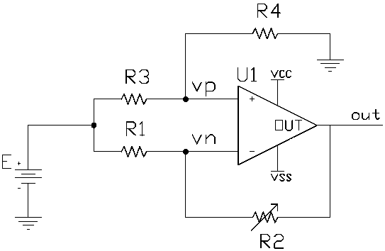
[0027] Such as figure 1 As shown, the present invention provides a resistance sensor measuring circuit for measuring weak signals, comprising: bridge arm resistance R3, bridge arm resistance R4, bridge arm resistance R1, resistance sensor R2, DC excitation voltage source, operational amplifier, and the bridge arm Resistor R3, bridge arm resistance R4, bridge arm resistance R1, resistance sensor R2 and operational amplifier form a balanced differential amplifier circuit structure. The measurement point of the reference bridge arm is connected to the non-inverting terminal of the operational amplifier, and the measurement point of the bridge arm where the resistance sensor R2 is located Connect the inverting terminal of the operational amplifier, the resistance sensor R2 is also used as the feedback resistance of the operational amplifier, and the output voltage change of the operational amplifier is proportional to the relative change rate of the resistance sensor R2.
[0028] ...
Embodiment 2
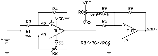
[0048] Such as Figure 4 As shown, the present invention provides another resistance sensor measurement circuit for measuring weak signals, including: differential resistance sensor R3, differential resistance sensor R4, reference resistance R1, reference resistance R2, DC excitation voltage source, operational amplifier, the The change directions of the differential resistance sensor R3 and the differential resistance sensor R4 are opposite, and the differential resistance sensor R3, the differential resistance sensor R4, the reference resistance R1, the reference resistance R2, and the operational amplifier form a balanced differential amplifier circuit structure, so The above-mentioned differential resistance sensor R3 and differential resistance sensor R4 form a bridge arm, and its measurement point is connected to the same-phase terminal of the operational amplifier; the reference resistance R1 and the reference resistance R2 form another bridge arm, and one of them is use...
Embodiment 3
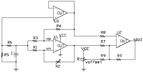
[0056] Such as Figure 5 As shown, the present invention also provides another resistance sensor measurement circuit for measuring weak signals, including: differential resistance sensor R4, differential resistance sensor R2, reference resistance R3, reference resistance R1, DC excitation voltage source, operational amplifier, and The change directions of the differential resistance sensor R4 and the differential resistance sensor R2 are opposite, the differential resistance sensor R4, the differential resistance sensor R2, the reference resistance R3, the reference resistance R1, and the operational amplifier form a balanced differential amplifier circuit structure, The reference resistor R3 and the differential resistance sensor R4 form a bridge arm, the reference resistor R1 and the differential resistance sensor R2 form another bridge arm, and the measurement points of the two bridge arms are respectively connected to the non-inverting terminal and the inverting terminal of...
PUM
 Abstract
Description
Claims
Application Information
 - R&D
- Intellectual Property
- Life Sciences
- Materials
- Tech Scout
- Unparalleled Data Quality
- Higher Quality Content
- 60% Fewer Hallucinations
Browse by: Latest US Patents, China's latest patents, Technical Efficacy Thesaurus, Application Domain, Technology Topic, Popular Technical Reports.
© 2025 PatSnap. All rights reserved.Legal|Privacy policy|Modern Slavery Act Transparency Statement|Sitemap|About US| Contact US: help@patsnap.com