Magnetic compatible tactile stimulator

A stimulator, magnetic compatibility technology, applied in medical science, using pressure for diagnosis, sensors, etc., can solve problems such as inability to achieve tactile spatial resolution, complex stimulator design, and air pressure instability.

Active Publication Date: 2020-01-10
ZHEJIANG UNIV
View PDF3 Cites 3 Cited by
  • Summary
  • Abstract
  • Description
  • Claims
  • Application Information

AI Technical Summary

Problems solved by technology

Due to the instability of air pressure, there are unpredictable changes in the force of the contact part with the skin
[0004] (2) The frequency range of tactile stimulation is limited
Based on the mechanical structure and the control mode of the pneumatic valve, the device can only achieve tactile stimulation below 6Hz
[0005] (3) Low spatial resolution of tactile stimuli
[0007] (1) The design of the stimulator is relatively complex and the spatial resolution is 1 cm, which cannot achieve fine tactile spatial resolution
[0008] (2) There is still a limited range of stimulation frequency below 130Hz, which cannot provide the full frequency range of stimulation that can be felt by human tactile receptors

Method used


Image

  • Magnetic compatible tactile stimulator
  • Magnetic compatible tactile stimulator
  • Magnetic compatible tactile stimulator

Examples


Embodiment 1

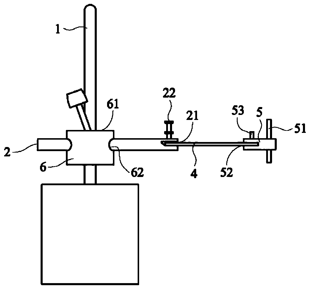
[0035] The magnetically compatible tactile stimulator provided in this embodiment includes:

[0036] The column 1 is vertically connected with the extension arm 2 through the connecting block 6;

[0037] The extension arm 2 is vertically connected with the column 1 through the connecting block 6, and moves up and down or rotates axially relative to the column 1;

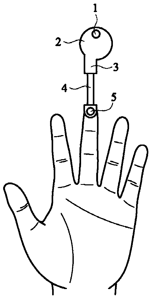
[0038] Ceramic piezoelectric sheet 4, one end is connected with extension arm 2, the other end is connected with stimulating element 5, and realizes vibrations of different intensities and frequencies under the control of the control unit;

[0039] The stimulus 5 is connected to the other end of the ceramic piezoelectric sheet 4, and swings up and down with the vibration of the ceramic piezoelectric sheet 4 to provide tactile stimulation to the subject;

[0040] The control unit is electrically connected to the ceramic piezoelectric sheet 4 and controls the vibration intensity and frequency of the ceramic piezoelect...

Embodiment 2

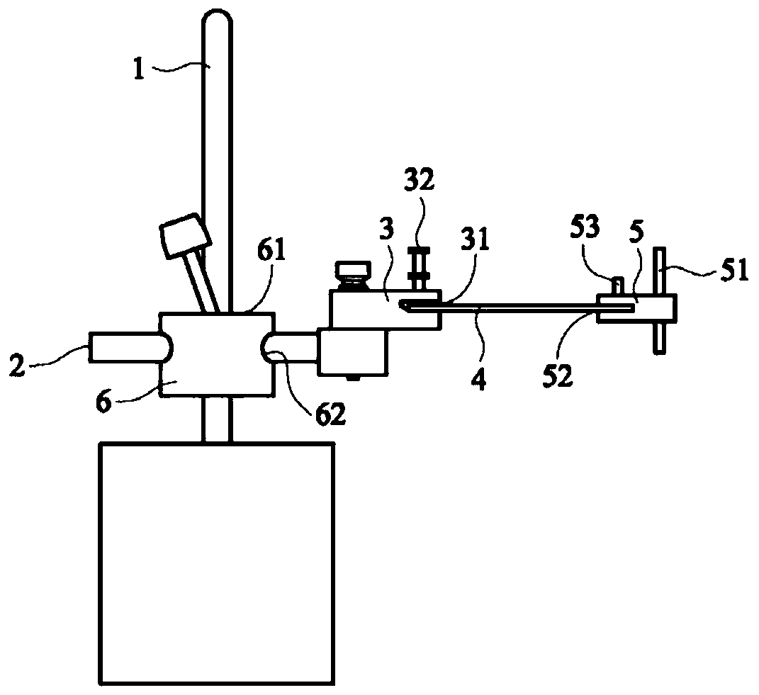
[0045] The magnetically compatible tactile stimulator provided in this embodiment includes:

[0046] The column 1 is vertically connected with the extension arm 2 through the connecting block 6;

[0047] The extension arm 2 is vertically connected with the column 1 through the connecting block 6, and moves up and down or rotates axially relative to the column 1;

[0048] Ceramic piezoelectric sheet 4, one end is connected with extension arm 2, the other end is connected with stimulating element 5, and realizes vibrations of different intensities and frequencies under the control of the control unit;

[0049] The stimulus 5 is connected to the other end of the ceramic piezoelectric sheet 4, and swings up and down with the vibration of the ceramic piezoelectric sheet 4 to provide tactile stimulation to the subject;

[0050] The control unit is electrically connected to the ceramic piezoelectric sheet 4 and controls the vibration intensity and frequency of the ceramic piezoelect...


PUM


Abstract

The invention discloses a magnetic compatible tactile stimulator, which comprises the components of a column which is connected with an extension arm; the extension arm, wherein the extension arm is connected with the column and moves up and down and back and forth or axially rotates relative to the column; a ceramic piezoelectric plate, wherein one end of the ceramic piezoelectric plate is connected with the extension arm, and vibration with different intensities and frequencies is realized under the control of a control unit; a stimulation part which is connected to the other end of the ceramic piezoelectric plate and swings up and down along with the vibration of the ceramic piezoelectric plate to perform tactile stimulation on a subject; and the control unit which is electrically connected with the ceramic piezoelectric plate and is used for controlling the vibration intensity and frequency of the ceramic piezoelectric plate. The magnetic compatible tactile stimulator provided by the invention can realize controllable tactile stimulation intensity in a magnetic resonance environment.

Description

technical field [0001] The invention belongs to the technical field of tactile stimulators, in particular to a magnetically compatible tactile stimulator. Background technique [0002] Since it is necessary to record the responses of relevant regions of the brain when receiving stimulation, it is necessary to use MRI technology to clearly capture the stimulation-induced image data of the whole brain function. However, when performing quantitative and controllable tactile stimulation with respect to the prior art, most of the equipment and equipment relied on cannot be carried out in the nuclear magnetic environment. At present, Zappe et al. have developed a magnetically compatible pneumatically driven tactile stimulation device, which uses pneumatic pressure to push the piston and drive the piston rod to move, so that the spherical plastic cap connected to the end of the piston rod contacts the skin, and finally restores the piston with the help of a spring The position of ...

Claims


Application Information

Patent Timeline
IPC IPC(8): A61B5/00
CPCA61B5/0053
Inventor 赖欣怡渠博艺
Owner ZHEJIANG UNIV
Why Eureka
Try Eureka