Staking bolt
一种螺栓、自锁的技术,应用在螺栓、螺钉、螺母等方向,能够解决螺母旋合、无法利用螺母固定等问题,达到牢固紧固的效果
Active Publication Date: 2020-01-07
AOYAMA SEISAKUSHO CO LTD
View PDF6 Cites 1 Cited by
- Summary
- Abstract
- Description
- Claims
- Application Information
AI Technical Summary
Problems solved by technology
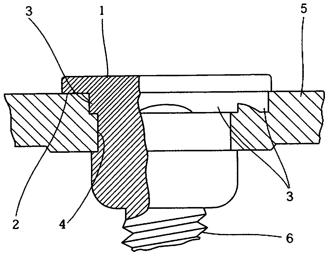
However, with such an existing structure, it is not easy to completely fill the interior of the annular groove 4 with metal material in the pressing process, and the idling torque after pressing is reduced to below 10 Nm.
In addition, the conventional self-locking bolt shown in Patent Document 1 has a large head 1, so it can only be pressed and fixed to a thick metal plate 5.
In addition, the conventional self-locking bolt shown in Patent Document 1 cannot screw the nut close to the head 1 because the head 1 is separated from the start position of the external thread 6 of the shaft. If the total thickness of the parts to be fastened is not thick enough, it cannot be fixed with nuts
Method used
View moreImage
Smart ImageViewing Examples
Examples
Embodiment
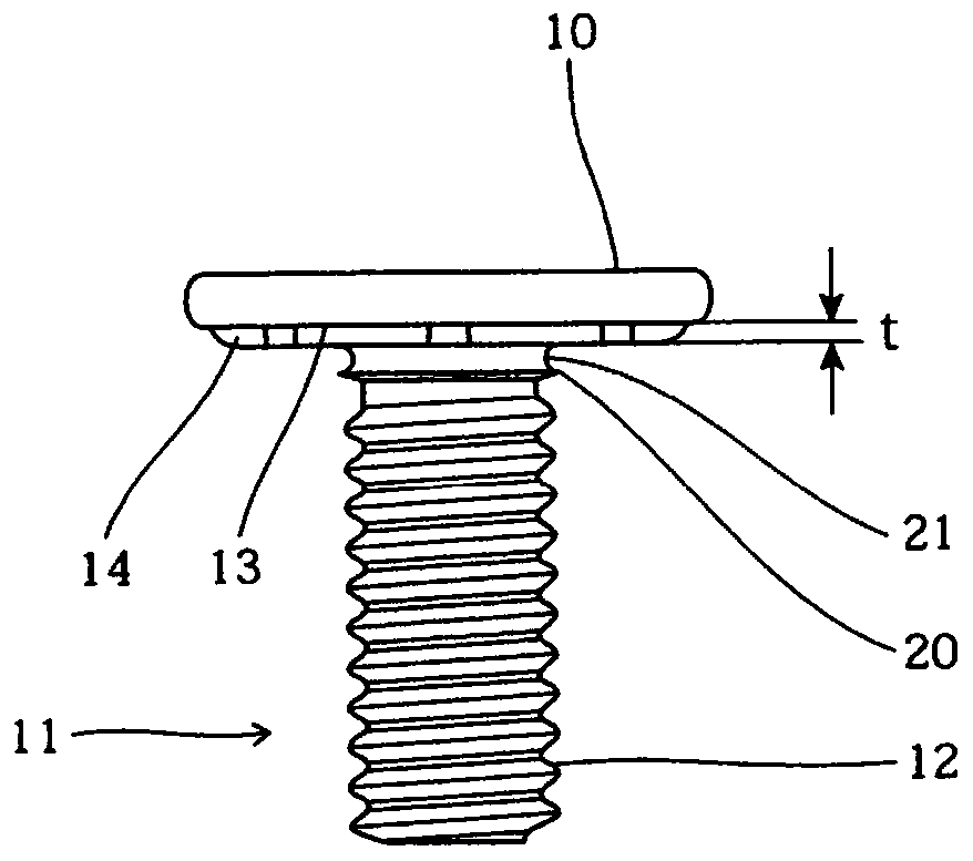
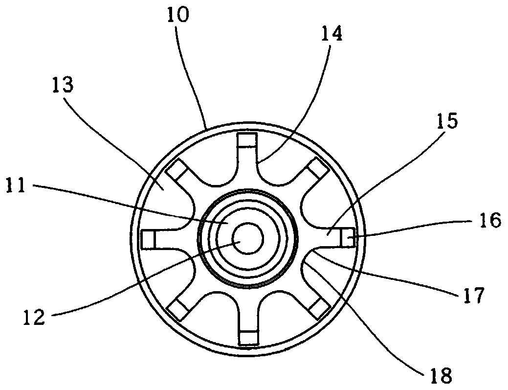
[0035] The self-locking bolt of the shape of the above-mentioned embodiment was manufactured in M6 size. Regarding the size of each site, the thickness of the head is 1.5 mm, t=0.5 mm, D=7.6 mm, d=6.3 mm, d1=4.55 mm, d2=4.7 mm, and d3=6.0 mm.
Login to View More PUM
 Abstract
This staking bolt comprises a head section 10 and a shaft section 11 on which an external thread 12 is formed. A ring-shaped protrusion 20 and a ring groove 21, which is located on the head-section side of the ring-shaped protrusion 20, are formed on the upper end of the shaft section 11. The head section 10 is flat, and a rotation-prevention protrusion 14, which is provided with a plurality of radial arm sections 15, protrudes at a thickness of t on the seating surface 13 of the head section. The minimum diameter D between the arm sections 15 is greater than the outer diameter d of the ring-shaped protrusion 20, and t*(D-d) / 2, which is the vertical cross-sectional area A of the minimum diameter section of the rotation-prevention protrusion 14, is greater than or equal to the vertical cross-sectional area of the ring groove 21.
Description
technical field [0001] The present invention relates to a self-locking bolt which is pressed and fixed to the surface of a metal plate as a target member for fastening other members. Background technique [0002] The self-locking bolt is a bolt that is press-fitted into a bottom hole of a metal plate as a target member with a tool, and plastically flows a metal material in an annular groove formed around a shaft, thereby being pressed and fixed to the metal plate. A larger pull-out load (pull-out load in the axial direction) is required for the self-locking bolt. In addition, compared with the self-locking bolt after being pressed and fixed, other parts are fastened and connected by nuts afterwards, so a larger idling torque (the torque at which the self-locking bolt starts idling relative to the metal plate) is desired, as shown in the patent As shown in Document 1, a self-locking bolt in which a rotation-preventing protrusion is formed on the contact surface of the head i...
Claims
Login to View More Application Information
Patent Timeline
 Patent Type & Authority Applications(China)
IPC IPC(8): F16B35/04F16B35/00F16B37/00F16B39/282
CPCF16B39/282F16B33/002F16B37/068F16B35/048
Inventor 星野直树古贺一博藤本孝典
Owner AOYAMA SEISAKUSHO CO LTD
Features
- R&D
- Intellectual Property
- Life Sciences
- Materials
- Tech Scout
- Unparalleled Data Quality
- Higher Quality Content
- 60% Fewer Hallucinations
Learn More Browse by: Latest US Patents, China's latest patents, Technical Efficacy Thesaurus, Application Domain, Technology Topic, Popular Technical Reports.
© 2025 PatSnap. All rights reserved.Legal|Privacy policy|Modern Slavery Act Transparency Statement|Sitemap|About US| Contact US: help@patsnap.com


