Central actuator for a hydraulic or pneumatic clutch actuation

A technology of pneumatic clutches and actuators, applied in the direction of fluid-driven clutches, non-mechanical-driven clutches, clutches, etc., can solve the problems of not so fast cooling and hardening, long residence time, etc., and achieve small dependence on dimensional tolerances and strengthen effect and dimensional stability, avoiding harmful structural changes

Pending Publication Date: 2020-01-07
FTE汽车有限责任公司
View PDF13 Cites 0 Cited by
  • Summary
  • Abstract
  • Description
  • Claims
  • Application Information

AI Technical Summary

Problems solved by technology

On the other hand, due to the heat storage capacity of the metal reinforcement, the plastic in the injection mold may not cool and harden as quickly, which leads to an undesirably relatively long residence time of injection molded workpieces in the injection mold in mass production time

Method used


Image

  • Central actuator for a hydraulic or pneumatic clutch actuation
  • Central actuator for a hydraulic or pneumatic clutch actuation
  • Central actuator for a hydraulic or pneumatic clutch actuation

Examples


Embodiment Construction

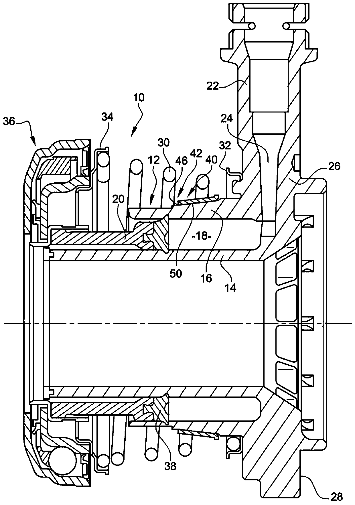
[0037] figure 1 The central release mechanism 10 for hydraulic clutch actuation of a dry friction clutch is shown in a dismounted state in a basic position. The central release mechanism 10 has an injection molded cylinder housing 12 made of plastic, such as GF-filled polyphthalamide, which has two concentrically arranged cylinder walls, an inner cylinder wall 14 and an outer cylinder wall 16, which An annular pressure chamber 18 is defined. An annular piston 20 , which can be operably connected to a clutch (not shown), is movably received in the pressure chamber 18 in the axial direction, which annular piston is optionally exposed to pressure via a pressure connection fitting 22 of the cylinder housing 12 . Medium, so that the friction clutch is disengaged by the movement of the annular piston 20. To this end, the pressure connection fitting 22 is connected to the pressure chamber 18 via a channel 24 formed in the cylinder housing 12 , so that the pressure medium, ie hydra...


PUM


Abstract

The invention relates to a central actuator (10) for a hydraulic or pneumatic clutch actuation, having a cylinder housing (12) which has at least one cylinder wall (14, 16) made of a plastic which delimits a ring-shaped pressure chamber (18) in a radial direction, in which a ring piston (20) that can be operatively connected to the clutch is displaceably received, wherein the cylinder wall (14, 16) is provided with at least one reinforcement ring (44, 46) on its peripheral side facing away from the compression chamber (18), wherein the reinforcement ring (46) is attached to the outside of theouter cylinder wall (16) and is divided in its axial extent into two abutting partial regions (46u, 46f), the first partial region (46u) whereof is surrounded on the outside by plastic from the cylinder housing (12) and the second partial region (46f) is free from plastic from the cylinder housing (12) on the outside.The invention further relates to a method of producing the cylinder housing (12)for a central actuator (10) of this kind.

Description

technical field [0001] The invention relates to a central actuator for hydraulic or pneumatic clutch actuation according to the preamble of claim 1 . In particular, the present invention relates to a central actuator for hydraulic clutch actuation of friction clutches of motor vehicles, as widely used in the motor vehicle industry. In this case, the central actuator can be configured as a central release mechanism or a central engagement mechanism or also as a double central engagement mechanism. Background technique [0002] Conventional hydraulic clutch actuation for motor vehicles has a master cylinder, operable eg by a clutch pedal, attached to a compensation tank filled with hydraulic fluid. The master cylinder is hydraulically connected to the slave cylinder by a pressure line, so that the pressure generated in the master cylinder by depressing the clutch pedal can be transmitted to the slave cylinder by a fluid column in the pressure line. As a result, the release b...

Claims


Application Information

Patent Timeline
IPC IPC(8): F16D25/08F16D25/12B29C45/14
CPCF16D25/08F16D25/14B29C45/14F16D2025/081F16D25/083F16D2300/10
Inventor J.尼普
Owner FTE汽车有限责任公司
Why Eureka
Try Eureka