Eureka AIR delivers breakthrough ideas for toughest innovation challenges, trusted by R&D personnel around the world.

Lens defect detection method based on stripe deflection

A defect detection and lens technology, applied in measurement devices, phase influence characteristic measurement, material analysis by optical means, etc., can solve the problems of easy introduction of human error, increase labor cost, slow manual detection speed, etc., and achieve high-precision detection. , the effect of simple structure

Inactive Publication Date: 2020-01-03
TIANJIN UNIV
View PDF7 Cites 6 Cited by
  • Summary
  • Abstract
  • Description
  • Claims
  • Application Information

AI Technical Summary

Problems solved by technology

However, in the process of processing, there are inevitably processing defects such as water marks and air bubbles.
Therefore, before the lens is officially put into use, it is necessary to introduce a testing process to avoid affecting the final performance of the device and causing irreparable losses
But the problem is that, first of all, the lens is a transparent material, and it is often difficult to directly photograph the defects
[0004] (1) From the perspective of production process and cost, manual inspection will introduce unnecessary additional links to production assembly, which is not conducive to the realization of fully automatic production assembly, and will also increase labor costs
[0005](2) From the perspective of production efficiency, the speed of manual inspection is relatively slow, and online inspection cannot be realized
[0006](3) From the perspective of testing results, the reliability of manual testing cannot be guaranteed, and it is easy to introduce human error

Method used


Image

  • Lens defect detection method based on stripe deflection
  • Lens defect detection method based on stripe deflection
  • Lens defect detection method based on stripe deflection

Examples


Embodiment Construction

[0024] The present invention will be described below with reference to the drawings and examples.

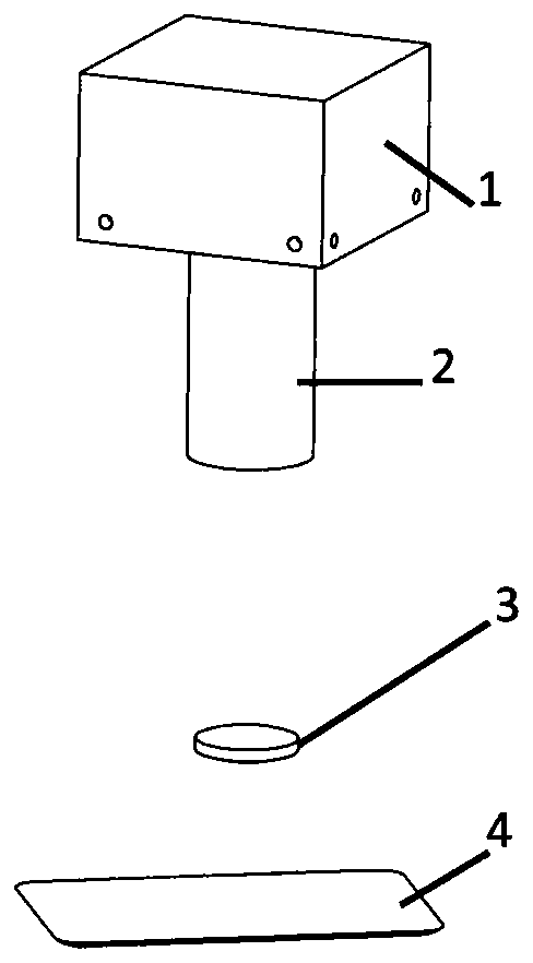
[0025] Such as figure 1 As shown, the main structures required by the lens defect detection method provided by the present invention include an industrial camera 1, a telecentric lens 2, and an LCD screen 4. The LCD screen is used to project sinusoidal fringes, the lens 3 is placed above the LCD screen, and the camera 1 shoots above the lens. The detection principle is as figure 2 As shown, when the lens 3 has a defect 5, it will inevitably affect the light refraction of the lens and cause the light to be deflected, as shown by the dotted line in the figure, which will cause the fringe image captured by the camera to change, and the specific fringe changes Such as image 3 Shown. Under normal circumstances, when the screen displays sinusoidal fringes, the camera will also capture uniform sinusoidal fringes 6 through the lens. When the lens is defective, it is reflected in the cam...


PUM


Abstract

The invention relates to a lens defect detection method based on stripe deflection. The method comprises the steps that a lens is placed above a screen, and a camera performs shooting above the lens;a shot image is utilized to make the screen display all white, and extraction of a region of interest in the lens is extracted through threshold segmentation; the screen is utilized to project sine stripes, and the camera takes a picture of the stripes refracted by a tested lens by aid of a telecentric lens; and defect recognition is performed in the region of interest, phase calculation is performed through a three-step phase shift method to acquire phase information, whether a phase jump exists or not is judged through calculation, and defect recognition and positioning are realized.

Description

Technical field [0001] The invention relates to a method for detecting micro lens defects Background technique [0002] Lens, as the most commonly used optical device, is widely used in industrial production and life. With the continuous expansion of demand, the lens has achieved mass production and automated production. However, in the processing process, processing defects such as water lines and bubbles are inevitable. Therefore, before the lens is officially put into use, it is necessary to introduce a detection process to avoid it affecting the final working performance of the equipment and causing irreparable losses. However, the problem is that, first of all, the lens is a transparent material, and it is often difficult to directly capture defects. Secondly, lens defects are often extremely small in size, and it is difficult to detect them by normal means. [0003] In the past, detection was often achieved through manual detection. However, manual detection has the foll...

Claims


Application Information

Patent Timeline
IPC IPC(8): G01N21/41G01N21/958
CPCG01N21/41G01N21/958G01N2021/4186G01N2021/9583
Inventor 张效栋闫宁潘进达朱琳琳
Owner TIANJIN UNIV
Why Eureka
Eureka Blog
Learn More