
A motor coupling with protection function

A protection function, coupling technology, applied in the direction of electromechanical devices, electrical components, electric components, etc., can solve the problems of increasing the maintenance cost of electromechanical equipment, no protection device for the coupling, shortening the service life of the motor, etc. The effect of manual reset, reducing load and prolonging service life

Active Publication Date: 2020-10-16
RONGCHENG HUAYU ELECTRIC CO LTD
View PDF6 Cites 0 Cited by
  • Summary
  • Abstract
  • Description
  • Claims
  • Application Information

AI Technical Summary

Problems solved by technology

[0003] Most of the current couplings for motors convert the rotation of the output shaft into the rotation of gears or rotating rods in all directions, and the transmission efficiency is high. However, most of the current couplings do not have protection devices. When the motor rotates to the maximum displacement, the motor Most of them will not be able to rotate due to the limitation of displacement, but the motor is still in working condition, which will cause the temperature of the motor to rise and the load to multiply, resulting in a greatly shortened service life of the motor and an increase in the maintenance cost of electromechanical equipment.

Method used


Image

  • A motor coupling with protection function
  • A motor coupling with protection function
  • A motor coupling with protection function

Examples


Embodiment Construction

[0020] The following will clearly and completely describe the technical solutions in the embodiments of the present invention with reference to the accompanying drawings in the embodiments of the present invention. Obviously, the described embodiments are only some, not all, embodiments of the present invention. Based on the embodiments of the present invention, all other embodiments obtained by persons of ordinary skill in the art without making creative efforts belong to the protection scope of the present invention.

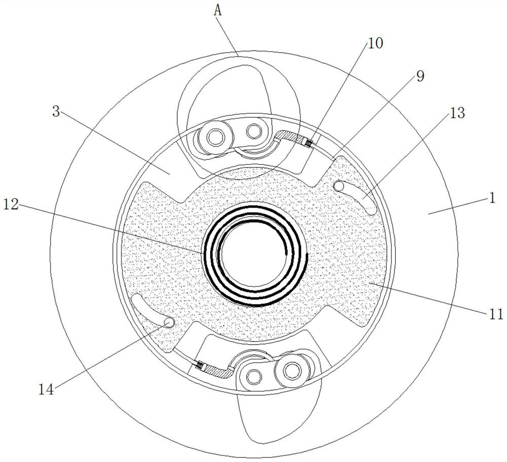
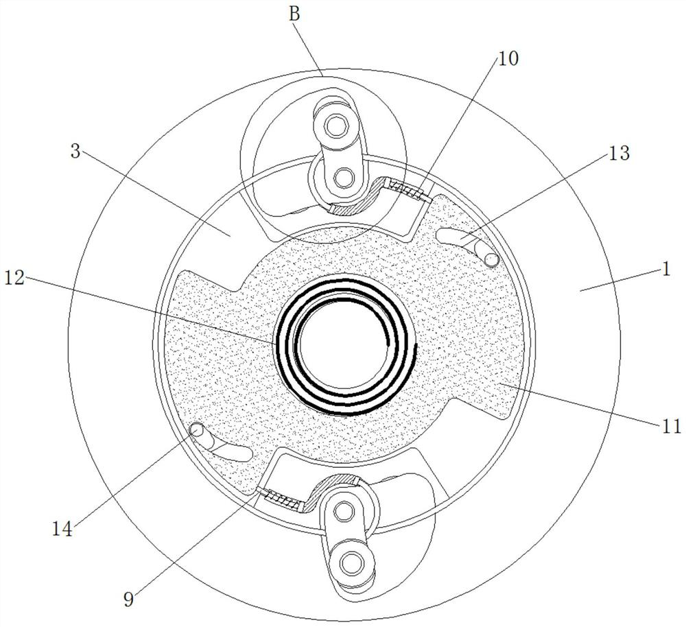
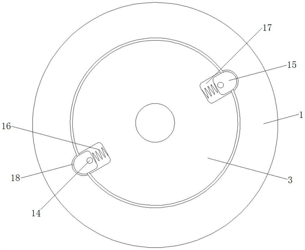
[0021] see Figure 1-5 , a motor coupling with protection function, including a housing 1, the housing 1 plays the role of fixed connection, the material of the housing 1 is steel material and the middle part of the housing 1 is provided with the output shaft 3 Adapted installation slots, the number of card slots 2 is two and the depth of the card slots 2 is not greater than the thickness of the housing 1, and the inner side of the housing 1 is provided with e...


PUM


Abstract

A motor shaft coupling with a protective function, which relates to the technical field of electromechanical equipment, includes a housing, the inner side of the housing is provided with evenly distributed card slots, the middle part of the housing is sleeved with an output shaft, and the outer side of the output shaft is The swivel connection has evenly distributed stops. The motor coupling with protective function is used through the cooperation of the stopper and the clamping block. The stopper is clamped with the housing in the initial state. When the motor is stuck, the stopper will be squeezed and shrunk into the output shaft. And the piston rod 2 protrudes under the hydraulic principle of the hydraulic tank, and pushes the rotary block to rotate clockwise. The rotary block drives the block to move to the inner side of the output shaft through the limit groove, so that the block shrinks into the output shaft, so that the There is no clamping connection between the output shaft and the housing. At this time, the output shaft can rotate normally in the middle of the housing, and the pulley on the stopper can reduce the friction force, thereby achieving the function of protecting the motor and reducing the friction. The load of the motor prolongs the service life of the motor.

Description

technical field [0001] The invention relates to the technical field of electromechanical equipment, in particular to a motor shaft coupling with protection function. Background technique [0002] Electromechanical equipment refers to automation equipment such as machinery or tools. Most electromechanical equipment is automated through motors, such as transmission devices. The motor drives the conveyor belt through the coupling to achieve the effect of automatic transmission. [0003] Most of the current couplings for motors convert the rotation of the output shaft into the rotation of gears or rotating rods in all directions, and the transmission efficiency is high. However, most of the current couplings do not have protection devices. When the motor rotates to the maximum displacement, the motor Most of them cannot rotate due to the limitation of displacement, but the motor is still in working condition, which causes the temperature of the motor to rise and the load to mult...

Claims


Application Information

Patent Timeline
Patent Type & Authority Patents(China)
IPC IPC(8): H02K7/10H02K5/04
CPCH02K5/04H02K7/10
Inventor 左方倩
Owner RONGCHENG HUAYU ELECTRIC CO LTD
Learn More