
Line recognition module and display equipment

A texture and module technology, applied in the field of texture recognition modules and display devices, can solve problems such as afterimages

Active Publication Date: 2019-12-31
BOE TECH GRP CO LTD
View PDF7 Cites 6 Cited by
  • Summary
  • Abstract
  • Description
  • Claims
  • Application Information

AI Technical Summary

Problems solved by technology

However, after-image phenomenon will occur when different light-emitting areas are illuminated at different times

Method used


Image

  • Line recognition module and display equipment
  • Line recognition module and display equipment
  • Line recognition module and display equipment

Examples


Embodiment Construction

[0040] Reference will now be made in detail to the exemplary embodiments, examples of which are illustrated in the accompanying drawings. When the following description refers to the accompanying drawings, the same numerals in different drawings refer to the same or similar elements unless otherwise indicated. The implementations described in the following exemplary examples do not represent all implementations consistent with the present invention. Rather, they are merely examples of apparatuses and methods consistent with aspects of the invention as recited in the appended claims.

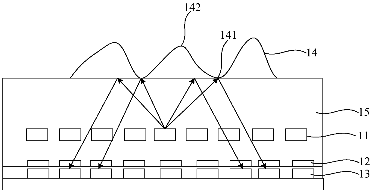
[0041] An embodiment of the present invention provides a texture recognition module. The texture recognition module can be used to recognize textures, such as fingerprints or palm prints. The texture recognition module includes: a light source array, an electrochromic device array and an image sensor array.

[0042]The electrochromic array is located between the light source array and the imag...


PUM


Abstract

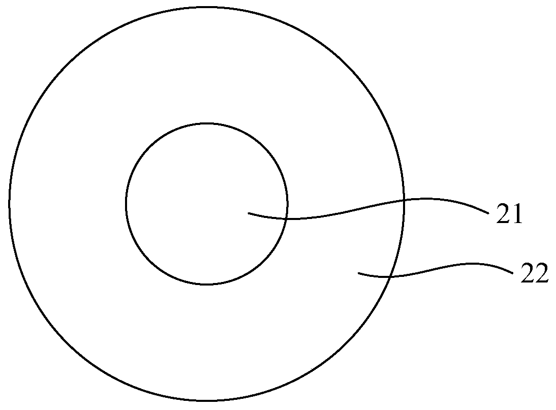
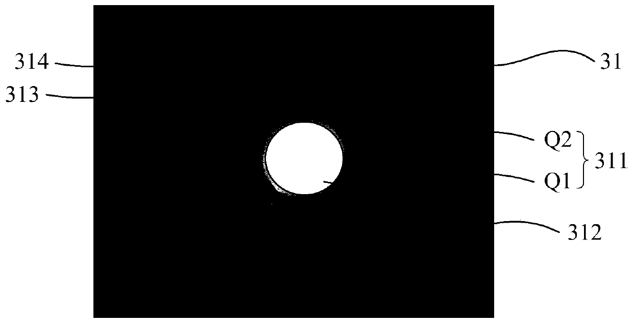
The invention relates to a line recognition module and display equipment. The line recognition module comprises a light source array, an electrochromic device array and an image sensor array, whereinthe electrochromic device array is located between the light source array and the image sensor array; the light source array comprises a plurality of light sources; the electrochromic device array comprises a plurality of electrochromic devices, and the image sensor array comprises a plurality of image sensors; the line recognition module is configured to emit light at a first moment in the firstlight emitting area in the line collection process; an imaging image of the first light-emitting area comprises a first non-imaging area and a first imaging area; and the electrochromism device in thefirst electrochromism area is in a shading state in the grain collecting process, so that light emitted from the light source and reflected by grains is prevented from reaching the first non-imagingarea, and the electrochromism device located outside the first electrochromism area is in a light-transmitting state. According to the embodiment of the invention, the residual image phenomenon occurring when the light source is lightened in a time-sharing manner can be eliminated.

Description

technical field [0001] The invention relates to the field of display technology, in particular to a texture recognition module and a display device. Background technique [0002] In related technologies, narrow-frame display technology has gradually become the mainstream. One of the means to realize this technology is to integrate an image sensor with fingerprint recognition function into the display screen to realize fingerprint recognition under the screen, so as to improve the display area of ​​the display screen. area. [0003] In the process of optical fingerprint recognition, when the distance between the operating body with lines such as fingers and the image sensor is relatively large, due to the scattering of light reflected by the operating body, the acquired image will be blurred, which will lead to The texture information identified by the received light is inaccurate. In order to solve the above problems, the light is usually modulated by a collimator to disti...

Claims


Application Information

Patent Timeline
IPC IPC(8): G06K9/00G02F1/153G02F1/155
CPCG02F1/153G02F1/155G06V40/13
Inventor 海晓泉
Owner BOE TECH GRP CO LTD
Learn More