Imaging lens and imaging apparatus
An imaging lens and lens technology, applied in optical components, instruments, optics, etc., can solve problems such as insufficient correction of distortion aberration, insufficient correction of distortion aberration and chromatic aberration of magnification, and achieve good performance and miniaturization
- Summary
- Abstract
- Description
- Claims
- Application Information
AI Technical Summary
Problems solved by technology
Method used
Image

Examples
Embodiment 1
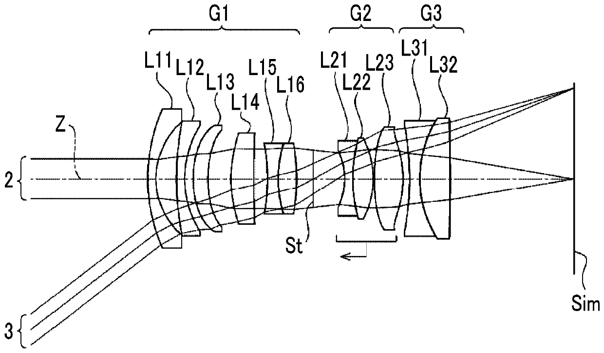
[0085] A cross-sectional view showing the structure of the imaging lens of Example 1 is at figure 1 It is shown in , and its illustration method and structure are as above, so a part of repeated description is omitted here. The imaging lens of Example 1 is sequentially composed of a first lens group G1 with positive refractive power, an aperture stop St, a second lens group G2 with positive refractive power, and a third lens group G3 with negative refractive power from the object side toward the image side. When focusing from an object at infinity to the closest object, only the second lens group G2 moves toward the object side along the optical axis Z. The above is the outline of the imaging lens of Embodiment 1.
[0086] The first lens group G1 is composed of six lenses of lenses L11 to L16 sequentially from the object side to the image side, the second lens group G2 is composed of three lenses of lenses L21 to L23 in sequence from the object side to the image side, and the...
Embodiment 2
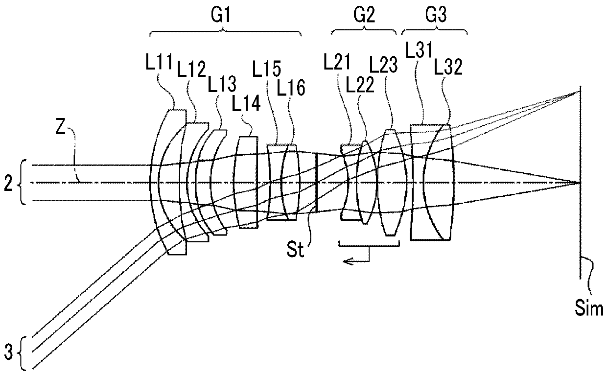
[0110] A sectional view showing the structure of the imaging lens of Example 2 is shown in figure 2 middle. The imaging lens of Example 2 has the same structure as that of the imaging lens of Example 1 in outline. The first lens group G1 is composed of six lenses of lenses L11 to L16 sequentially from the object side to the image side, the second lens group G2 is composed of three lenses of lenses L21 to L23 in sequence from the object side to the image side, and the third lens group G3 is composed of two lenses of lenses L31 to L32 sequentially from the object side toward the image side. The basic lens data of the imaging lens of Example 2 are shown in Table 4, the various factors are shown in Table 5, the aspheric coefficients are shown in Table 6, and the various aberrations in the state of focusing on an object at infinity are illustrated. At Figure 7 middle.
[0111] [Table 4]
[0112] Example 2
[0113] sn R D Nd vd θgF 1 46.21544 2.400 1...
Embodiment 3
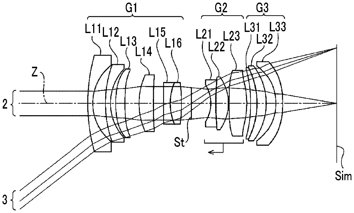
[0121] A sectional view showing the structure of the imaging lens of Example 3 is shown in image 3 middle. The imaging lens of Example 3 has the same structure as that of the imaging lens of Example 1 in outline. The first lens group G1 is composed of 6 lenses of lenses L11 to L16 in sequence from the object side to the image side, the second lens group G2 is composed of 3 lenses of lenses L21 to L23 in sequence from the object side to the image side, and the third lens group The group G3 is composed of three lenses of lenses L31 to L33 in order from the object side toward the image side. The basic lens data of the imaging lens of Example 3 are shown in Table 7, the various factors are shown in Table 8, the aspheric coefficients are shown in Table 9, and the various aberration diagrams of the state of focusing on an object at infinity shown in Figure 8 middle.
[0122] [Table 7]
[0123] Example 3
[0124] sn R D Nd vd θgF 1 90.84269 2.400 1.60...
PUM
 Abstract
Description
Claims
Application Information
 - R&D
- Intellectual Property
- Life Sciences
- Materials
- Tech Scout
- Unparalleled Data Quality
- Higher Quality Content
- 60% Fewer Hallucinations
Browse by: Latest US Patents, China's latest patents, Technical Efficacy Thesaurus, Application Domain, Technology Topic, Popular Technical Reports.
© 2025 PatSnap. All rights reserved.Legal|Privacy policy|Modern Slavery Act Transparency Statement|Sitemap|About US| Contact US: help@patsnap.com