Method and device for controlling pressure during aerated dual-gradient drilling for riser

A riser and dual gradient technology, which is applied in the automatic control system of drilling, drilling equipment, earth-moving drilling and production, etc., can solve the problems of stuck drilling, inability to effectively change the bottom hole pressure, drilling fluid leakage, etc., and achieve increased pressure regulation The effect of range, increased adjustment precision and timely responsiveness

Active Publication Date: 2019-12-27
SOUTHWEST PETROLEUM UNIV
View PDF18 Cites 0 Cited by
  • Summary
  • Abstract
  • Description
  • Claims
  • Application Information

AI Technical Summary

Problems solved by technology

[0002] With the intensification of offshore oil and gas exploration and development, drilling in various complex areas is increasing, and the application of conventional drilling technology in these areas may lead to many drilling problems: a large amount of drilling fluid loss caused by leaky formations, blowout accidents, Pipe sticking and other downhole complex accidents; at the same time, it will also cause damage to the production zone
Compared with long-distance well sections, the amount of air charged cannot effectively change the bottomhole pressure in a short period of time, let alone make timely and effective responses to the ever-changing actual engineering conditions

Method used


Image

  • Method and device for controlling pressure during aerated dual-gradient drilling for riser
  • Method and device for controlling pressure during aerated dual-gradient drilling for riser
  • Method and device for controlling pressure during aerated dual-gradient drilling for riser

Examples


Embodiment Construction

[0017] The present invention will be further described below in conjunction with accompanying drawing:

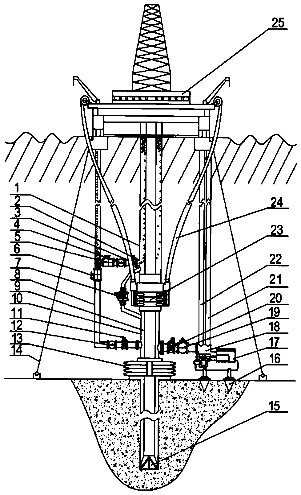
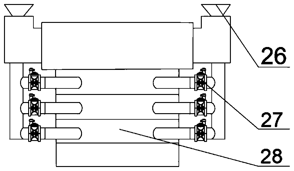
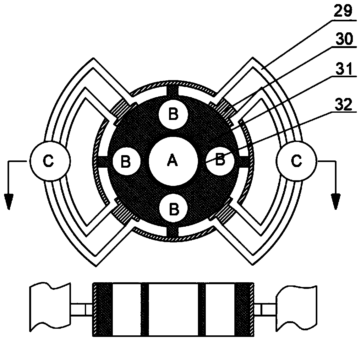
[0018] Such as Figure 1-Figure 5 As shown, a method and device for controlling pressure in riser-inflated dual-gradient drilling are schematically composed of an upper riser 1, an emergency shut-off solenoid valve A2, an upper gas injection channel 3, a one-way valve A4, and an automatic high-pressure control valve A5 , automatic high-pressure control valve B6, balance communication device 7, lower gas injection channel 8, drill pipe 9, lower riser 10, emergency shut-off solenoid valve B11, one-way valve B12, blowout preventer 13, fixed chain 14, drill bit 15, Fixer 16, monitoring and analysis module 17, subsea high-pressure pump 18, voltage stabilizer 19, emergency cut-off solenoid valve C20, booster pipeline 21, pressure-reducing pipeline 22, locking device 23, high-pressure hydraulic oil delivery pipe 24 and drilling platform 25, characterized in that: the upper riser ...


PUM


Abstract

The invention discloses a structure diagram of a method and device for controlling a pressure during aerated dual-gradient drilling for a riser. The device is mainly composed of an upper-part riser, an upper gas-injection channel, a balance communication device, a lower gas-injection channel, a drill rod, a lower-part riser, a blowout preventer, a seabed high-pressure pump, a pressure stabilizer,an emergency cut-off electromagnetic valve C, a blocking device, a high-pressure hydraulic oil conveying pipe and a drilling platform, wherein the upper-part riser extends downwards from the drillingplatform, the lower-part riser extends downwards from the blocking device, and the high-pressure hydraulic oil conveying pipe is arranged on the blocking device; an upper port of the balance communication device is connected with the upper-part riser above the blocking device, and a lower port of the balance communication device is connected with the lower-part riser below the blocking device; theblowout preventer is arranged at a seabed well mouth; the emergency cut-off electromagnetic valve C is arranged in a pipeline of the seabed high-pressure pump, and a pressure reduction pipeline and apressure increasing pipeline are arranged on the seabed high-pressure pump. The device is capable of accurately controlling a bottom-hole pressure in time, and adaptive to varied actual engineering conditions, so that the safe progress of deep sea drilling is ensured.

Description

technical field [0001] The patent of the present invention relates to riser-inflated dual-gradient drilling, in particular to a method and device for controlling pressure in riser-inflated dual-gradient drilling. Background technique [0002] With the intensification of offshore oil and gas exploration and development, drilling in various complex areas is increasing, and the application of conventional drilling technology in these areas may lead to many drilling problems: a large amount of drilling fluid loss caused by leaky formations, blowout accidents, Drill sticking and other downhole complex accidents; at the same time, it will also cause damage to the production layer. Drilling in many areas of our country, the non-operating drilling time is mainly caused by lost circulation, blowout and other downhole complex accidents. Especially in the process of drilling, a large amount of drilling fluid is often leaked, or even leaked and lost, causing blowout accidents, causing ...

Claims


Application Information

Patent Timeline
IPC IPC(8): E21B44/00E21B47/06
CPCE21B44/00E21B47/06
Inventor 祝效华冉亮敬俊汤历平
Owner SOUTHWEST PETROLEUM UNIV
Why Eureka
Try Eureka