
Hedge shears

A hedge and scissor blade technology, applied in the direction of trimming hedge equipment, applications, cutting tools, etc., can solve the problems of inability to prevent impact loads, limit the service life of the slip ring transmission mechanism, etc., and achieve improved operability, light weight and light weight. effect of noise

Inactive Publication Date: 2003-04-23
ROBERT BOSCH GMBH
View PDF5 Cites 0 Cited by
  • Summary
  • Abstract
  • Description
  • Claims
  • Application Information

AI Technical Summary

Problems solved by technology

This seriously limits the service life of the slip ring transmission mechanism
[0006] In addition, this transmission mechanism of the known machine cannot prevent possible shock loads when the saw blade is locked.

Method used


Image

  • Hedge shears
  • Hedge shears
  • Hedge shears

Examples


Embodiment Construction

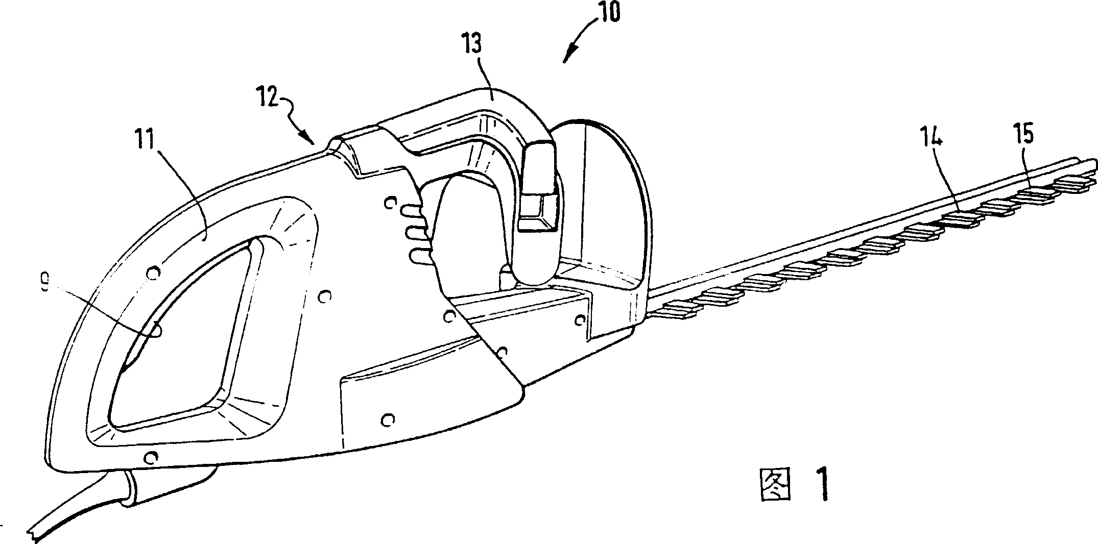
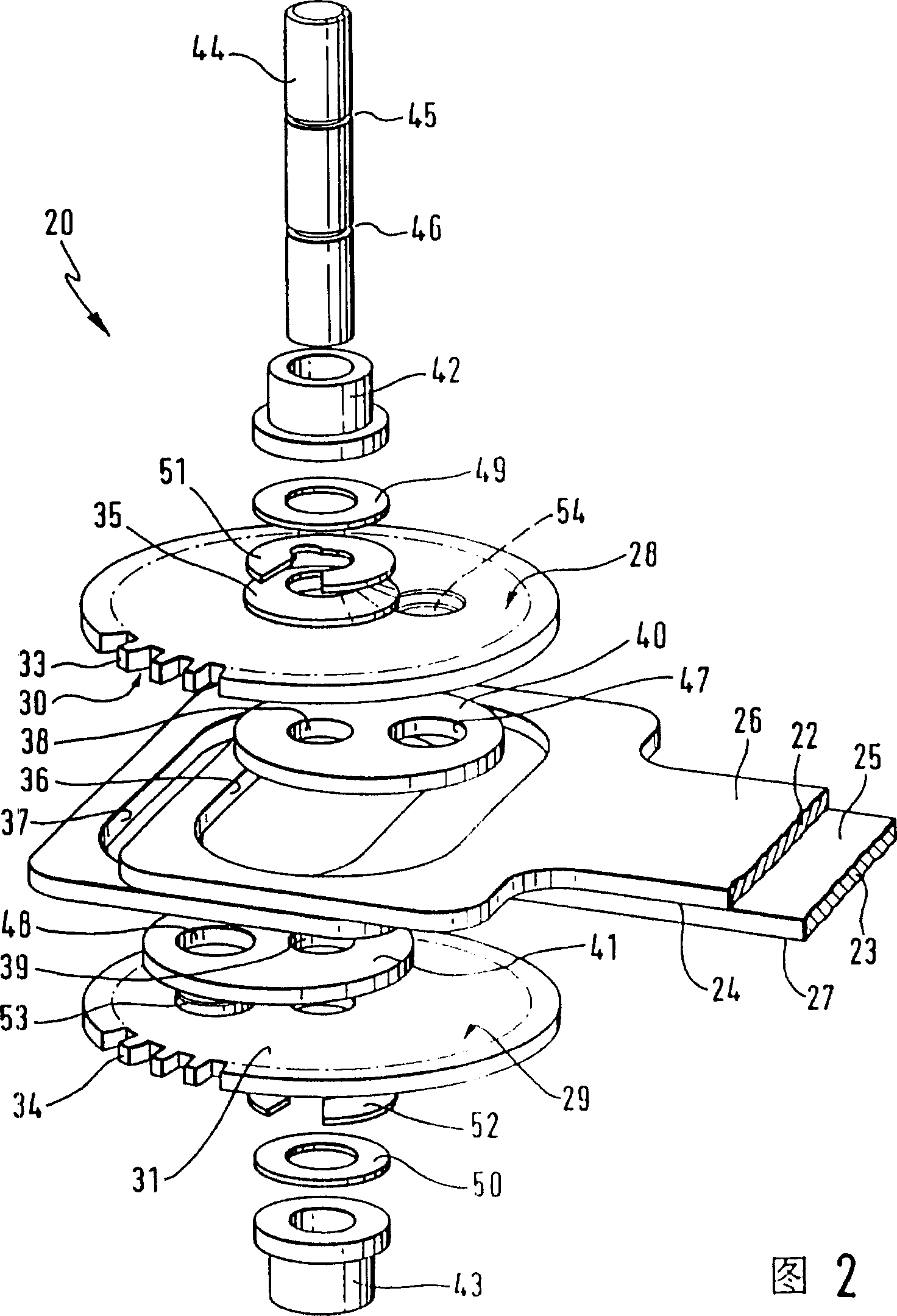
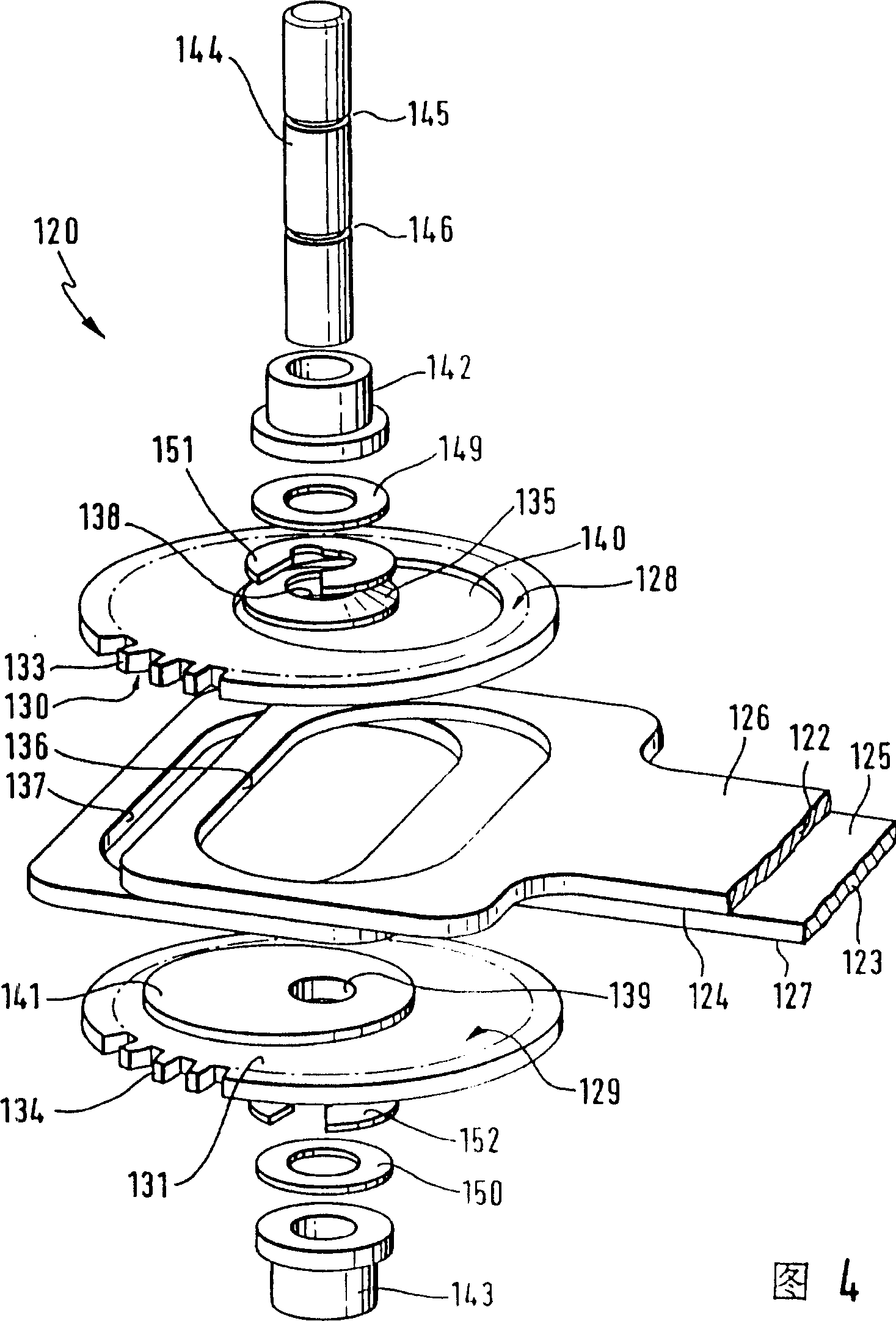
[0020] The hedge shears 10 shown in Fig. 1 has a shell 12, with a first handle 11 and a second handle 13 on the shell 12, the first handle 11 has a button 9 of an electric working switch not shown in the figure, longitudinally from the shell to the front Extend the hedge shear blade pairs 14, 15. This pair of blades 14, 15 is driven to and fro by an unrepresented motor mounted in the housing 12. The rotary motion of motor shaft 16 is transformed into the reciprocating motion of hedge shear blades 14,15 by motor driving pinion 18 and by slip ring transmission mechanism 20 shown in Fig. 2,4 or 6.

[0021] As can be clearly seen from the exploded view of the slip ring transmission mechanism 20 shown in FIG. 2 , the ends of the hedge shears blades 14 , 15 on the side where the housing is located are connected with the slip ring tool holders 22 , 23 . The tool holders 22, 23 are mounted directly adjacent to each other. When the hedge shears 10 are in operation, their inner planar...


PUM


Abstract

Two transmission gears of the sliding transmission mechanism of a motor-driven hedge shear are arranged parallel at interval on a shaft. Crank pins of eccentrically arranged disks are arranged at the face-to-face side faces of the gears; a knife rest surrounding the crank pins like crescent is guided between the gears; each crank pin passes through a first hole to surround the shaft and is driven to rotate by the adjoining gear because of the connection between them.

Description

technical field [0001] The present invention relates to a hedge shear. Background technique [0002] Known from DE-OS 3638376 is a motor-driven tool, ie a saw, with two saw blades that move back and forth. This saw has a slip ring drive mechanism through which the rotation of the motor shaft is converted to the reciprocating motion of the saw blade. The slip ring drive is formed by a central spur gear meshing with the drive pinion of the motor shaft and mounted in a torsionally connected manner on a shaft mounted in the drive housing. The spur gear is inserted into the crescent-shaped recess of the two slip-ring-shaped tool holders by means of a crank pin designed as an eccentric pin protruding from its two flat sides. These two circular eccentric pins just drive the knife rest, and thus drive the saw blade to do reciprocating linear motion. [0003] In the known mechanical slip ring transmission mechanism, the area where the eccentric pin is located is relatively easy to...

Claims


Application Information

Patent Timeline
IPC IPC(8): A01G3/04A01G3/053B23D49/00B27B19/00
CPCB23D49/006A01G3/053
Inventor P·海伍德H·阿特津特T·M·J·布劳瓦斯
Owner ROBERT BOSCH GMBH
Learn More