Wiring connector

A technology of connectors and cables, which is applied in the direction of connection, clamping/spring connection, parts of connection devices, etc., can solve the problem of low assembly efficiency of wiring connectors, achieve the effect of convenient installation and improve assembly efficiency

Inactive Publication Date: 2019-12-24
CHINA AVIATION OPTICAL-ELECTRICAL TECH CO LTD
View PDF9 Cites 4 Cited by
  • Summary
  • Abstract
  • Description
  • Claims
  • Application Information

AI Technical Summary

Problems solved by technology

[0004] The purpose of the present invention is to provide a wiring connector to solve the problem of low assembly efficiency of existing wiring connectors

Method used


Image

  • Wiring connector
  • Wiring connector
  • Wiring connector

Examples


Embodiment Construction

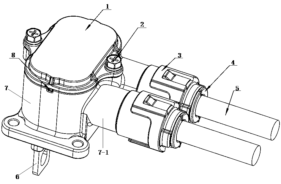
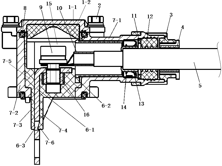
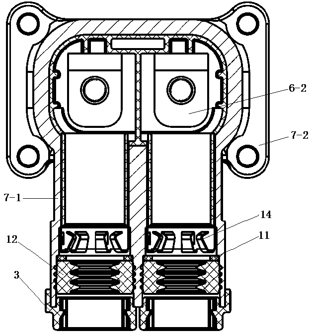
[0022] An example of the wiring connector in the present invention is Figure 1~Figure 8 As shown, it includes a base 7 and an upper cover 1 that is buckled and connected with the base 7. The base 7 and the upper cover 1 together form a wiring cavity 15. The upper cover 1 includes an upper cover housing 1-1 and an upper cover housing 1. The upper cover insulator 1-2 in -1, the base 7 includes a base shell 7-2 and a base insulator 7-5 arranged in the base shell 7-2, wherein the base shell 7-2 includes an integrally formed front and rear The cylinder section 7-1 extending in the direction, the cylinder section 7-1 communicates with the wiring cavity 15, the inner hole of the cylinder section 7-1 constitutes a threading hole for the cable 5 to pass through, so that the cable 5 end The connection terminal 10 protrudes into the connection cavity 15 from the back to the front.

[0023] In order to facilitate the wiring and improve the assembly efficiency of the wiring connector, th...


PUM


Abstract

The invention provides a wiring connector which comprises a base and an upper cover relatively fastened to the base. One of the base and the upper cover is provided with a cylinder body section through which a cable passes. Inside the cylinder body section, a wire sealing body which sleeves the cable is installed. The tail end of the cylinder body section is provided with a tail cover for the cable to pass through, and the tail cover blocks the wire sealing body in the cylinder body. An anti-swinging washer which sleeves the cable to prevent the cable from being bent excessively is arranged inthe tail cover. The anti-swaying washer comprises at least two petal rings surrounding a complete ring. The anti-swaying washer is snap-connected with the tail cover through a snap structure on the anti-swaying washer to prevent falling off in the axial direction. The wiring connector has the advantages that the tail cover does not need to sleeve the cable when wiring is carried out; the gap between the inner wall of the tail cover and the cable can allow the cable to pass through the cylinder section smoothly; after the cable is installed, multiple petal rings directly wrap and surround thecable to form a complete circle, and then are arranged in the tail cover and snap-connected with the tail cover; the installation is very convenient; and the assembly efficiency of the wiring connector is greatly improved.

Description

technical field [0001] The invention relates to a wiring connector. Background technique [0002] At present, electric vehicles mostly use shielded wires. When producing harnesses, in order to facilitate the wiring, cable accessories such as the tail cover and the sealing body of the wiring connector are usually directly installed on the housing of the wiring connector, thereby reducing the number of wires on the wiring harness. Reduce the number of parts, improve the production efficiency of the wire harness, and reduce the risk of damage to the cable accessories during the turnaround of the wire harness and the assembly process. For example, the electrical connector (i.e., wiring connector) disclosed in the Chinese utility model patent with the authorized announcement number CN206685565U, the wiring connector includes a socket housing and a plug housing (i.e., a base and an upper cover) that is hermetically sealed with the socket housing. There is a cylinder connected to ...

Claims


Application Information

Patent Timeline
Patent Type & Authority Applications(China)
IPC IPC(8): H01R13/502H01R13/512H01R13/52H01R13/56H01R13/648H01R13/424H01R13/02H01R4/30
CPCH01R4/30H01R13/02H01R13/424H01R13/502H01R13/512H01R13/5202H01R13/562H01R13/648
Inventor 岳梦龙娄鹏李璞郭辉
Owner CHINA AVIATION OPTICAL-ELECTRICAL TECH CO LTD
Why Eureka
Try Eureka