A glass production and manufacturing conveying line

An assembly line and glass technology, which is applied to conveyors, conveyor objects, transportation and packaging, etc., can solve the problems of inconvenient glass removal, low return efficiency, and inconvenience to manually take glass, etc. The effect of saving power loss and saving investment

Active Publication Date: 2020-07-10
江苏辛巴新材料科技股份有限公司
View PDF12 Cites 0 Cited by
  • Summary
  • Abstract
  • Description
  • Claims
  • Application Information

AI Technical Summary

Problems solved by technology

[0003] In the process of glass production and manufacturing, the processed glass needs to be transferred to the packaging area for packaging and packaging, so as to facilitate temporary storage and later transportation. Some of the transfer process uses manual transfer. Manual transfer is inefficient and very troublesome. Some use glass The conveying device is used for transfer, but the belt conveyor is generally used for transfer and transportation. Because the surface of the glass itself is smooth and easy to condense into water mist on the surface, the glass is easily adsorbed on the conveyor belt, which is inconvenient to remove the glass from the conveyor belt during the transportation process. In addition, the glass is basically placed horizontally during the conveying process and the glass is relatively thin, so it is not convenient to take the glass manually

Method used


Image

  • A glass production and manufacturing conveying line
  • A glass production and manufacturing conveying line
  • A glass production and manufacturing conveying line

Examples


Embodiment Construction

[0022] The specific embodiment of the present invention will be described in further detail by describing the embodiments below with reference to the accompanying drawings, the purpose is to help those skilled in the art to have a more complete, accurate and in-depth understanding of the concept and technical solutions of the present invention, and To facilitate its practice, but not as a limitation of the invention.

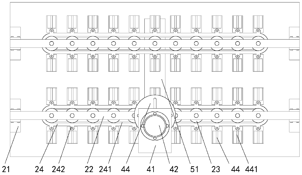
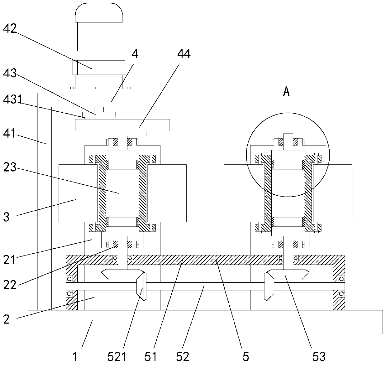
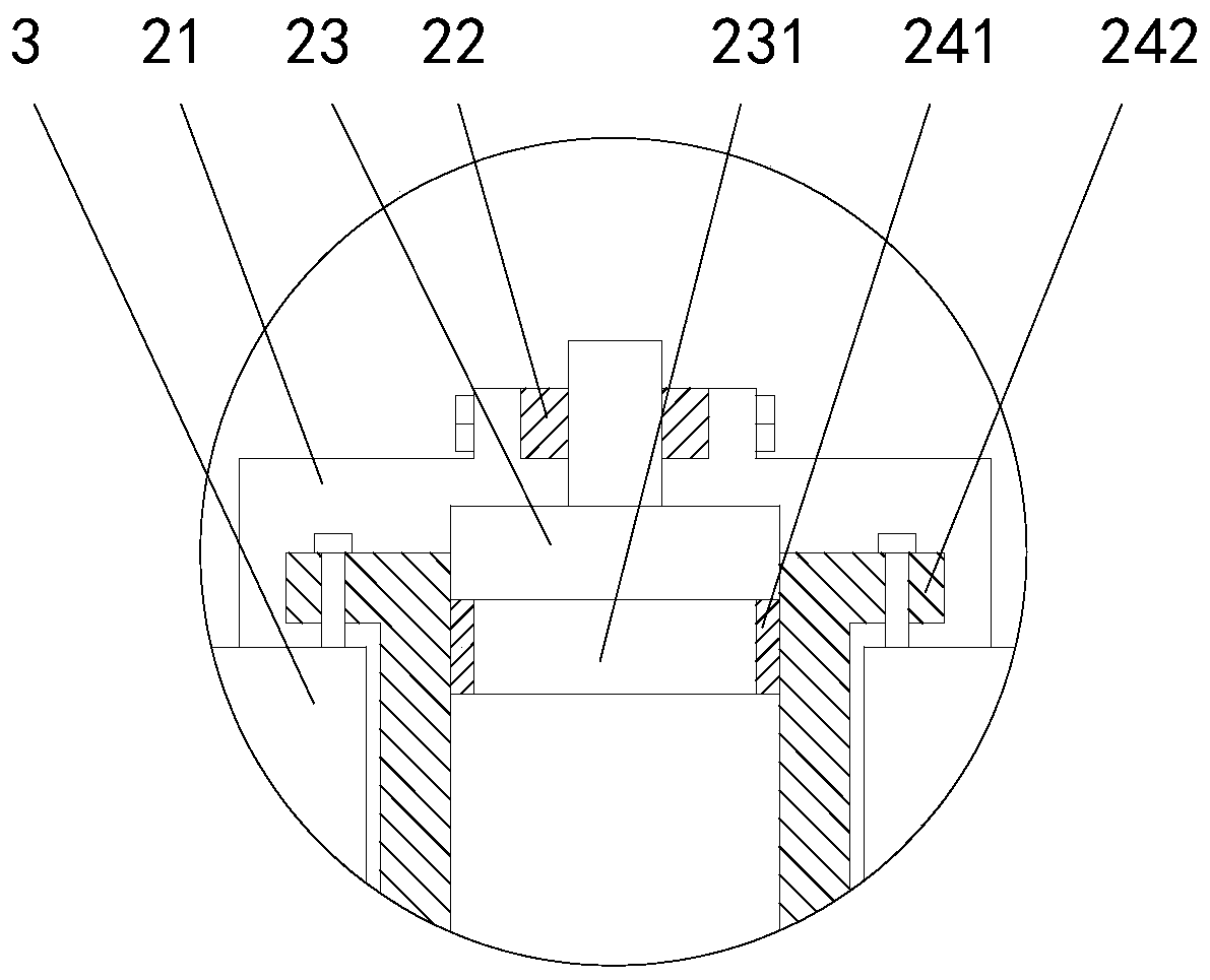
[0023] See attached Figure 1-5 As shown, a glass manufacturing and conveying line includes a base 1, two belt conveyors 2 installed in parallel on the base 1, a glass support plate 3 for placing glass, an intermittent drive mechanism 4 and a continuous The driving mechanism 5, the belt conveyor 2 includes eleven rotating rollers 23 evenly distributed along a straight line and the conveyor belts 24 sleeved on all the rotating rollers 23, the rotating rollers 23 are vertically rotated, and the two conveyor belts 24 An equal number of glass support plates 3 are e...


PUM


Abstract

The invention relates to a glass production and manufacturing conveying assembly line. The line comprises a base, two belt conveying devices which are arranged on the base in parallel, glass bearing plates for placing and bearing glass, am intermittent driving mechanism and a linkage mechanism, wherein each belt type conveying device comprises a plurality of rotating rollers uniformly distributedin a linear mode and a conveying belt arranged on all rotating rollers in a sleeve mode, the rotating rollers are vertically arranged in a rotating mode, the glass bearing plates of equal number are uniformly distributed on the two conveying belts, the intermittent driving mechanism can drive the rotating rollers located in the middle of one belt type conveying device to rotate intermittently, andthe linkage mechanism comprises a rotary frame fixedly installed on the base, a linkage rotating shaft which is installed on the rotary frame in a horizontal rotating mode and two linkage bevel gears. According to the conveying assembly line, the glass is vertically delivered, operation workers are combined to carry out flowing conveying, so that glass taking by workers in the glass flowing transferring and conveying process is greatly facilitated, and the line is more humanized.

Description

technical field [0001] The invention relates to the technical field of equipment related to glass processing, and specifically proposes a glass manufacturing and conveying line. Background technique [0002] Glass is an amorphous inorganic non-metallic material, generally made of various inorganic minerals (such as quartz sand, borax, boric acid, barite, barium carbonate, limestone, feldspar, soda ash, etc.) As an important building material, it can be seen everywhere in life and has been widely used. [0003] In the process of glass production and manufacturing, the processed glass needs to be transferred to the packaging area for packaging and packaging, so as to facilitate temporary storage and later transportation. Some of the transfer process uses manual transfer, which is inefficient and very troublesome. Some use glass The conveying device is used for transfer, but the belt conveyor is generally used for transfer and transportation. Because the surface of the glass i...

Claims


Application Information

Patent Timeline
Patent Type & Authority Patents(China)
IPC IPC(8): B65G49/06B65G17/12B65G17/26B65G17/32
CPCB65G17/123B65G17/26B65G17/32B65G49/063
Inventor 孙思宇何海峰
Owner 江苏辛巴新材料科技股份有限公司
Why Eureka
Try Eureka