
Massaging device

A technology of moving base and track plate, applied in roller massage, massage auxiliary products, physical therapy and other directions, can solve the problem of single structure of massage bed, and achieve the effect of improving microcirculation, correcting spine, and high massage comfort.

Inactive Publication Date: 2019-12-20
重庆咏寿堂健身器材有限公司
View PDF0 Cites 0 Cited by
  • Summary
  • Abstract
  • Description
  • Claims
  • Application Information

AI Technical Summary

Problems solved by technology

[0004] There are certain defects in the design of existing massage beds. Generally, the structure of massage beds is single, and it is impossible to make changes according to the different requirements of the bending range of different positions of the massage bed in the lying position of the human body, so as to provide the best comfort and function.

Method used


Image

  • Massaging device
  • Massaging device
  • Massaging device

Examples


Embodiment 1

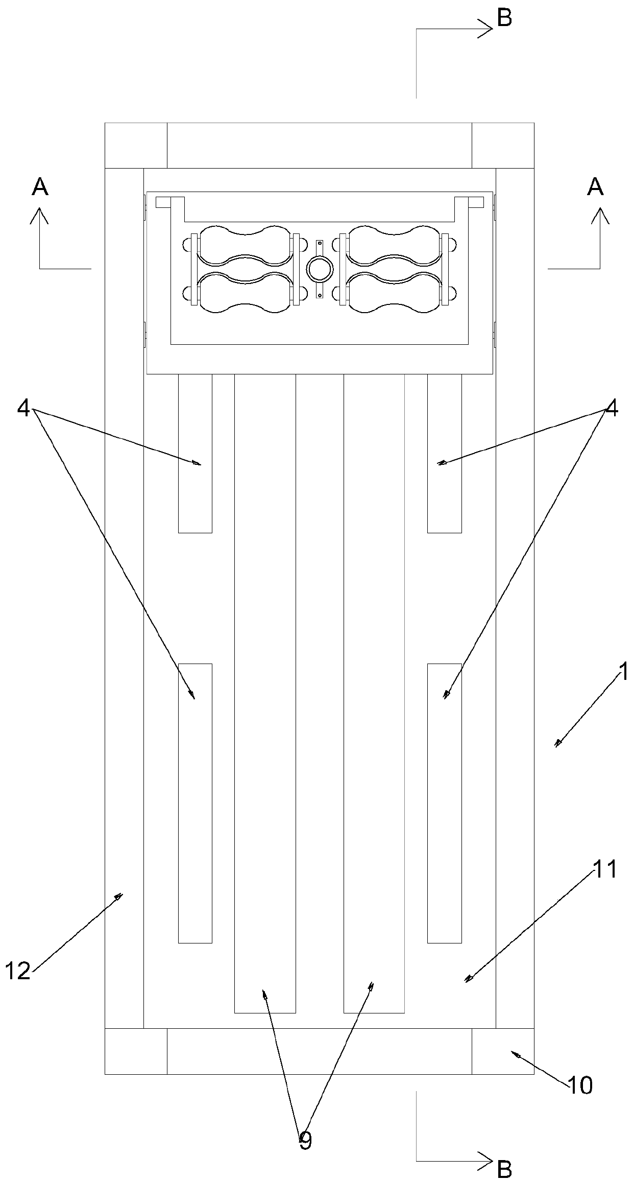
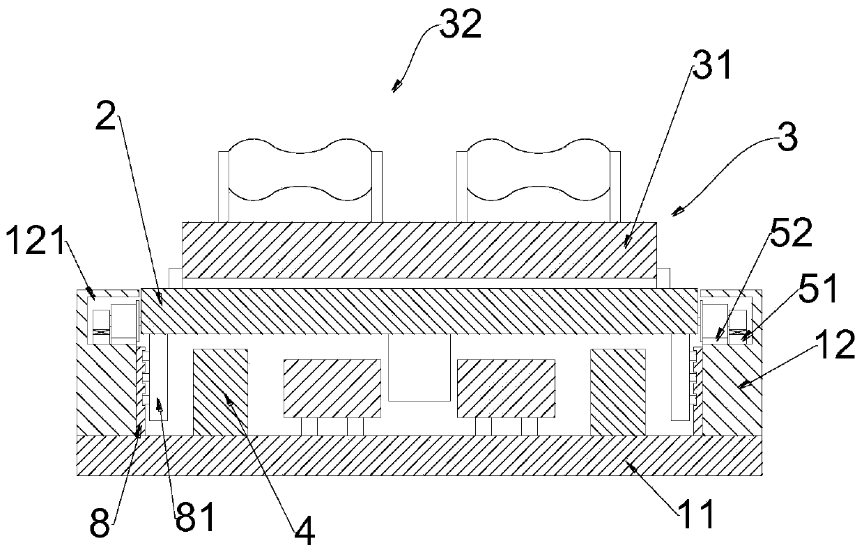
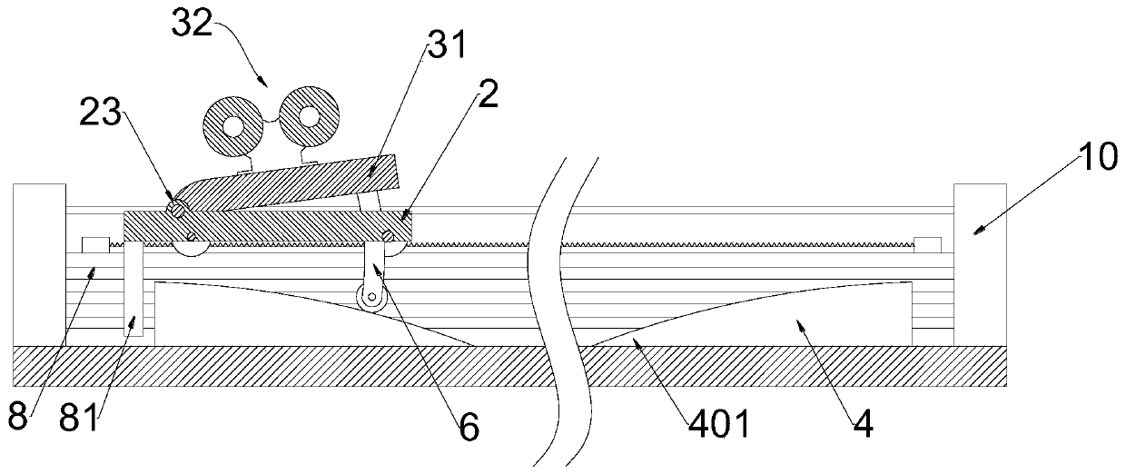
[0037] refer to figure 1 and figure 2 , is a massage device of the present invention, specifically, the massage device includes a bed frame 1, a mobile base 2, a massage mechanism 3 and a track plate group 4, and the bed frame 1 includes a base plate 11 and a base plate arranged in parallel on the base plate 11. Two side plates 12 are provided with a guide rail group; the mobile base 2 is placed on the guide rail group through a set of walking wheels, and the mobile base 2 moves and cooperates with the bed frame 1 through the driving mechanism 7; the track plate group 4 Set on the bottom plate 11; the massage mechanism 3 includes a massage assembly 32 and a seat plate 31, the massage assembly 32 is installed on the seat plate 31, the seat plate 31 is rotatably connected to the mobile base 2, and the bottom of the seat plate 31 is provided with a sliding support rod group 6. The seat plate 31 and the mobile base 2 are rotated through the cooperation of the sliding support rod...

Embodiment 2

[0051] In this embodiment, the structure, connection relationship and working principle of each component are the same as in Embodiment 1, the difference is that, refer to Figure 9 , in this embodiment, the track plate group 4 includes a track plate body 40 and a track base 45, the track plate body 40 is slidably connected to the track base 45; , the anti-retraction mechanism includes a ratchet part arranged on the track plate body 40 and a ratchet part arranged on the track base 45, and the ratchet part meshes with the ratchet part.

[0052] The track plate group 4 in the present embodiment comprises fin-shaped track plate body 40 and track base 45 two parts, and track base 45 is generally installed on the bottom plate 11 of physiotherapy bed, and the bottom of track plate body 40 is then slidably arranged on the track base 45, in order to make the track plate body 40 and the track base 45 relatively fixed after installation, the ratchet part is set on the track plate body 4...


PUM


Abstract

The invention relates to the field of body-building apparatuses, and particularly discloses a massaging device. The massaging device comprises a bed body framework, a moving base, a massaging mechanism and a railway plate group, wherein the movable base is placed on a guide rail group through a group of travelling wheels; the moving base is in moving cooperation with the bed body framework througha driving mechanism; the railway plate group is arranged on the bottom plate; a seat plate is rotatably connected to the moving base; a sliding supporting rod group is arranged at the bottom of the seat plate; and the seat plate and the moving base cooperate with the railway plate group through the sliding supporting rod group to realize rotation. According to the massaging device disclosed by the invention, through the cooperation of truckles arranged on the sliding supporting rod group and the arc-shaped railway plate group, the lifting of the massaging assembly is realized; the massaging device is simple in structure and smooth in guidance; and in the advancing process of the massaging mechanism, rising and falling of the massaging assembly can be realized.

Description

technical field [0001] The invention relates to the field of fitness equipment, in particular to a massage device. Background technique [0002] With the rapid economic development, people's life, study and work pressure continue to increase. For a long time, people have been studying and working with their heads down for a long time, but they have neglected their own health, and their understanding and attention to their cervical spine are far from enough. As a result, many people now suffer from lumbar spine diseases, so many prevention and treatment Products for lumbar diseases emerged as the times require, including massage tables. The massage table is the product of the combination of traditional Chinese medicine and modern technology. It is a pure physical massage method. It combines the four traditional physical massage methods of "heat therapy, traction, massage, and exercise" into a fitness equipment, forming a superimposed multiplication Effect, realize the passi...

Claims


Application Information

Patent Timeline
Patent Type & Authority Applications(China)
IPC IPC(8): A61H15/00
CPCA61H15/0078A61H2015/0021
Inventor 张勇
Owner 重庆咏寿堂健身器材有限公司
Learn More