
Mine transportation equipment provided with safety slow speed device and safe operation method thereof

A technology of slowing device and transportation equipment, which is applied in hoisting devices, transportation and packaging, elevators, etc., and can solve the problems of tank damage, easy failure of fall arresters, inadequate maintenance of fall arresters or brake ropes, etc.

Pending Publication Date: 2019-12-17
MAGNA MAGNETOMOTIVE CO LTD
View PDF0 Cites 2 Cited by
  • Summary
  • Abstract
  • Description
  • Claims
  • Application Information

AI Technical Summary

Problems solved by technology

The protection measures for the existing cages in the case of broken ropes mainly rely on the fall arrester and the buffer device at the bottom of the tank. Due to the complex environment of the coal mine, and the lack of maintenance of the fall arrester or brake rope, the fall arrester is prone to failure , at this time, the free fall of the cage directly hits the buffer platform at the bottom of the tank, there is basically no possibility of survival for the personnel, and the tank body will also be damaged under huge energy

Method used


Image

  • Mine transportation equipment provided with safety slow speed device and safe operation method thereof
  • Mine transportation equipment provided with safety slow speed device and safe operation method thereof
  • Mine transportation equipment provided with safety slow speed device and safe operation method thereof

Examples


Embodiment Construction

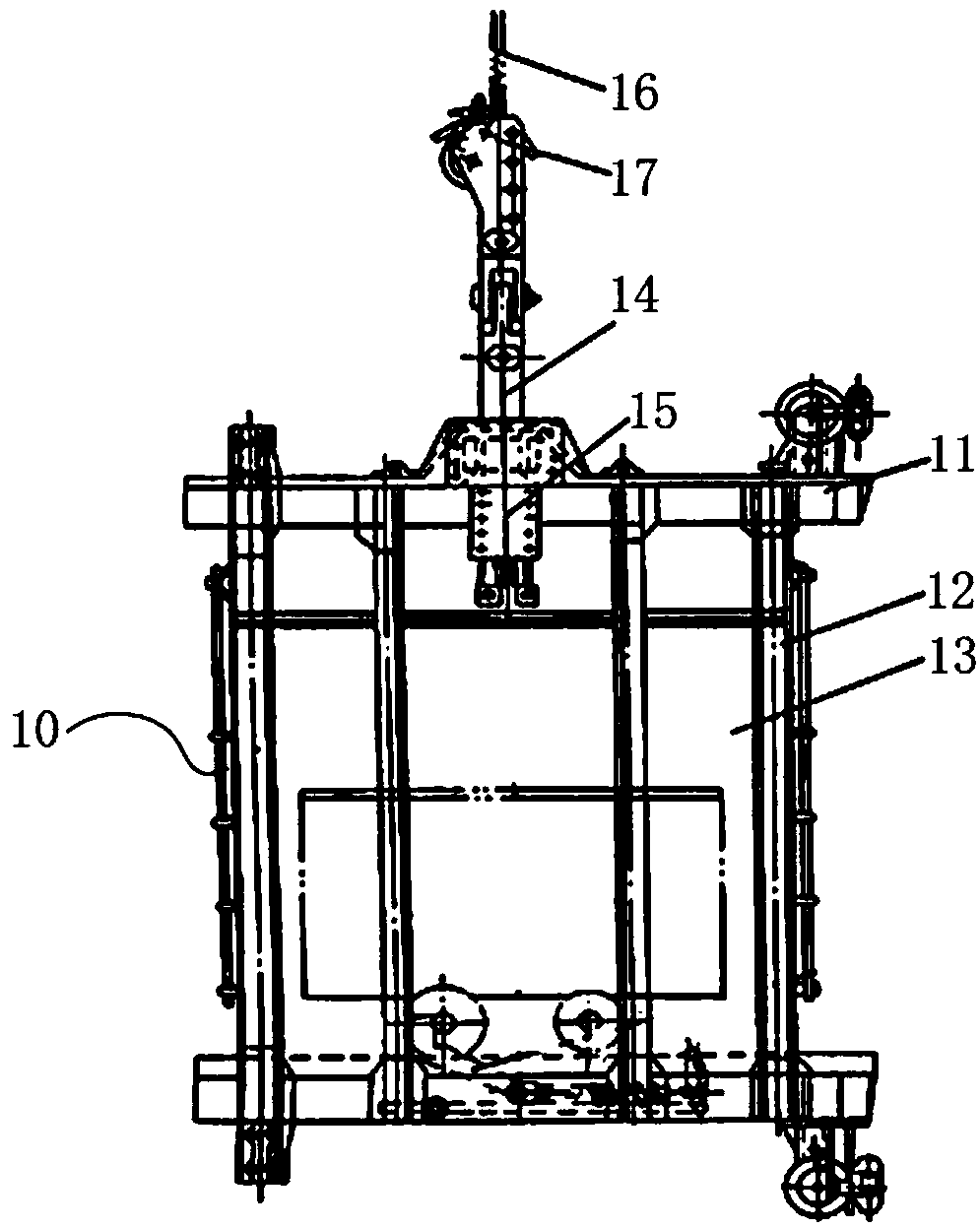
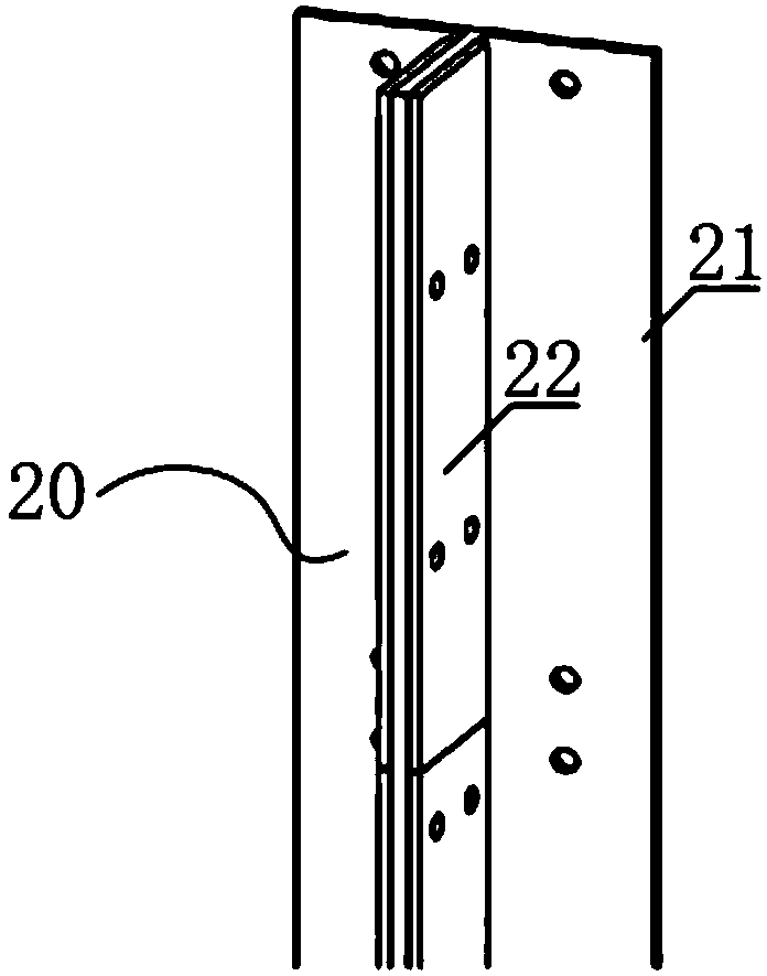
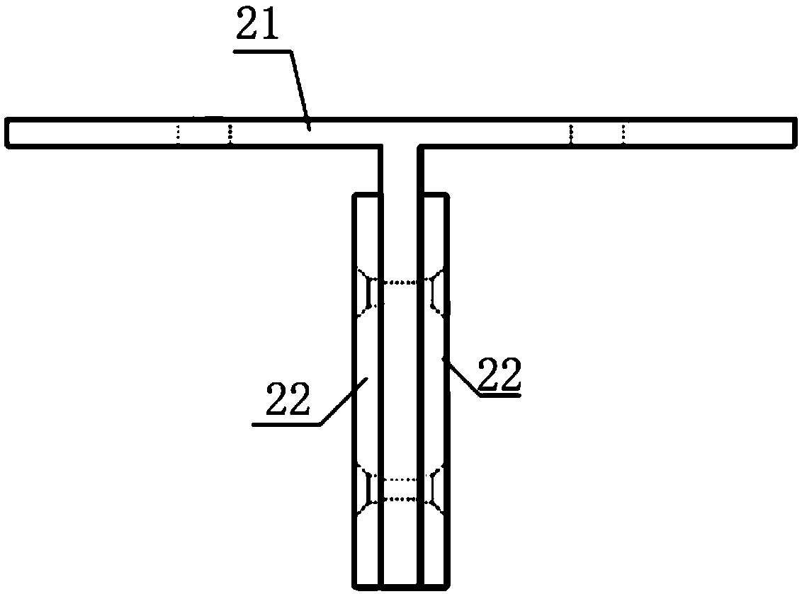
[0030] Hereinafter, embodiments of mine transportation equipment provided with a safety retarder and its safe operation method of the present invention will be described with reference to the accompanying drawings.

[0031] The examples described here are specific specific implementations of the present invention, and are used to illustrate the concept of the present invention. They are all explanatory and exemplary, and should not be construed as limiting the implementation of the present invention and the scope of the present invention. In addition to the embodiments described here, those skilled in the art can also adopt other obvious technical solutions based on the claims of the application and the contents disclosed in the description, and these technical solutions include adopting any obvious changes made to the embodiments described here. Replacement and modified technical solutions.

[0032] The accompanying drawings in this specification are schematic diagrams, which...


PUM


Abstract

The invention discloses mine transportation equipment provided with a safety slow speed device and a safe operation method thereof. The mine transportation equipment comprises a cage, a slow speed guide rail, a permanent magnet retarder and a trigger device, wherein the slow speed guide rail comprises a guide rail body and a metal cover plate, and the metal cover plate is fixedly connected with the side surface of the guide rail body; the permanent magnet retarder is fixedly connected with the cage; a permanent magnetic braking unit of the permanent magnet retarder is arranged on the side surface of the slow speed guide rail, and in a non-triggering state, the interval distance between the permanent magnetic braking unit and the slow speed guide rail is a non-braking distance; and the trigger device is connected with a lifting steel wire rope, and when the lifting steel wire rope breaks, the trigger device drives the permanent magnetic braking unit of the permanent magnet retarder to be close to the slow speed guide rail so that the interval distance between the permanent magnet braking unit and the slow speed guide rail can meet a braking gap. The transport equipment has the advantages of being simple in principle, reliable in action, and high in reliability and capable of ensuring the safety of personnel in the cage under the condition of cage failing; and moreover, based onthe working characteristics of the equipment, a cage body is prevented from being damaged after falling of the cage, so that the production loss of an enterprise is reduced.

Description

technical field [0001] The invention belongs to the technical field of mine transportation equipment and mine safety transportation, and in particular relates to a mine transportation equipment equipped with a safety retarder and a safe operation method of the mine transportation equipment. Background technique [0002] Modern engineering construction, construction and mining are inseparable from hoisting machinery. Mine hoists are responsible for the tasks of lifting ore along the shaft, lowering materials, lifting personnel and equipment, and occupy an extremely important position in mining production activities. The role of mine hoisting determines that the hoist must have the characteristics of safety, reliability, high efficiency and economy. Mine production requires that the hoisting equipment can operate safely and reliably for a long time, and minimize the accident rate and maintenance time; at the same time, the hoist is a large-scale mining equipment with high pow...

Claims


Application Information

Patent Timeline
IPC IPC(8): B66B5/18B66D5/24
CPCB66B5/18B66D5/24
Inventor 马忠威陈德民柴士伟王骏王文慧
Owner MAGNA MAGNETOMOTIVE CO LTD
Learn More