Castor and endoscope trolley

An endoscope and caster technology, applied in the field of medical equipment, can solve the problems of trolley adjustment, large vibration of the trolley, unfavorable equipment of the trolley, etc., and achieve the effect of simple locking action and good shock absorption effect.

Active Publication Date: 2019-12-13
重庆金山医疗技术研究院有限公司
View PDF10 Cites 3 Cited by
  • Summary
  • Abstract
  • Description
  • Claims
  • Application Information

AI Technical Summary

Problems solved by technology

It has the following problems: 1. The rotating shaft connecting the caster and the trolley frame does not pass through the center of the caster, which causes the trolley to be adjusted in the forward and backward direction first, and then to the left and right. Adjust the position of the trolley internally; 2. The brakes on multiple casters need to be locked one by one to realize the fixation of the trolley. The locking action is complicated, and it is not easy to step on the brakes in a small space; 3. In the flatness When moving on poor ground, the trolley will generate large vibrations, which is not good for the equipment on the trolley

Method used


Image

  • Castor and endoscope trolley
  • Castor and endoscope trolley
  • Castor and endoscope trolley

Examples


Embodiment 1

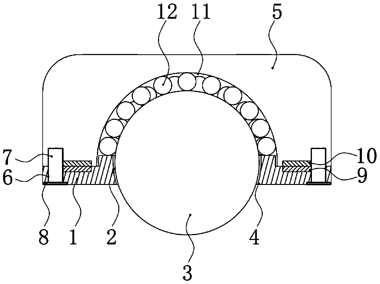
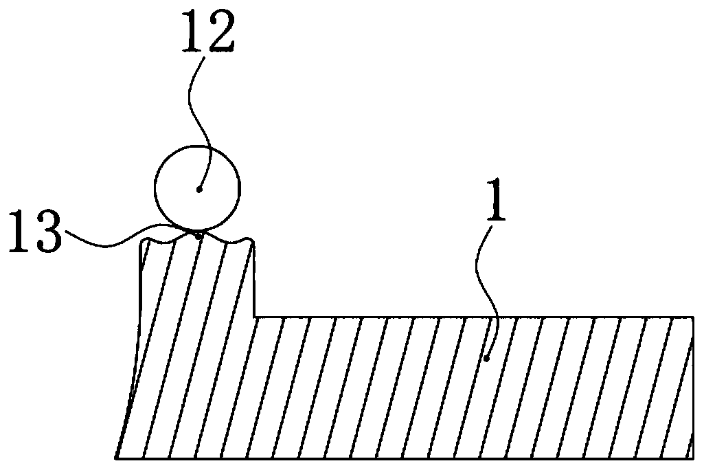
[0026] Such as figure 1 The caster shown includes a support base 1, and the middle part of the support base 1 is provided with a vertically penetrating installation hole 2, and a rolling ball 3 is provided in the installation hole 2, and the diameter of the rolling ball 3 is slightly smaller than that of the installation hole 2. Aperture, the thickness of the support seat 1 is about 1 / 3 of the diameter of the ball 3, and the lower part of the support seat 1 is provided with a limit stop edge 4 for preventing the ball 3 from falling out of the lower end of the installation hole 2. The limit stop edge 4 It is annular and arranged coaxially with the mounting hole 2 , the diameter of the hole surrounded by the limit stop edge 4 is smaller than the diameter of the rolling ball 3 , and the ball center of the rolling ball 3 is higher than the limit stop edge 4 .

[0027] Such as figure 1 As shown, the supporting seat 1 is provided with a connecting seat 5 acting on the rolling ball ...

Embodiment 2

[0033] The structural principle of this embodiment is basically the same as that of Embodiment 1, the difference is that there are a number of vertically arranged connecting holes 6 on the connecting base 5, and the number of connecting holes 6 is fixed on the supporting base 1. Corresponding to the connecting column 7, the connecting column 7 is pierced in the corresponding connecting hole 6, and the upper end of the connecting column 7 is provided with a limit flange 8 whose outer diameter is larger than that of the connecting hole 6. Wherein, the connecting holes 6 are distributed in a circular array along the centerline of the mounting holes 2 .

Embodiment 3

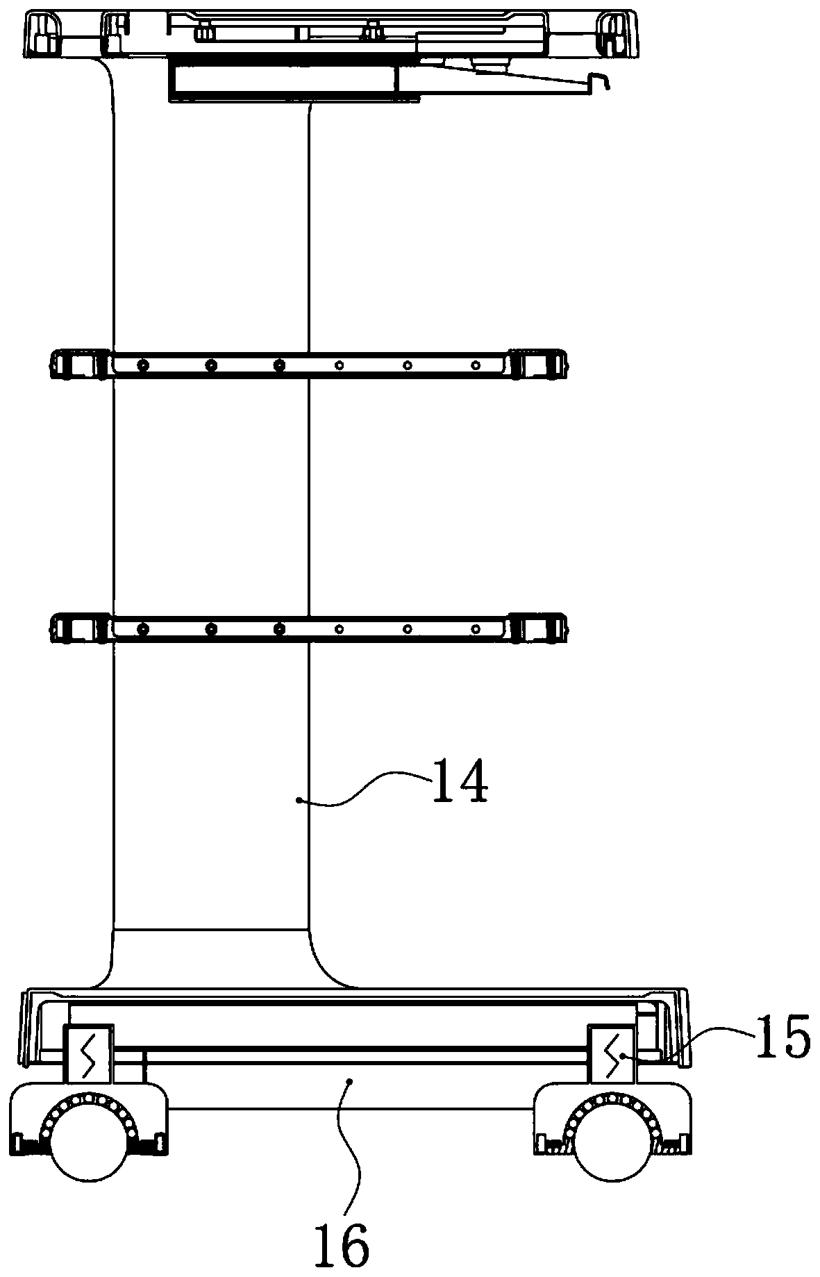
[0035] Such as image 3 The shown endoscope trolley includes a trolley frame 14, the bottom of the trolley frame 14 is provided with four casters as described in Embodiment 1 or Embodiment 2, and between each caster and the trolley frame 14 A damper 15 attenuates the vibration and acts as a shock absorber.

[0036] Such as image 3 As shown, a power supply 16 is provided on the trolley frame 14, and the power supply 16 is an uninterruptible power supply 16 (UPS), which can provide power for equipment placed on the trolley, such as an image processor and a cold light source, and simultaneously provide power for the drive in the casters. Components provide power. A locking / unlocking button is provided on the trolley frame 14 for controlling the driving components in the casters.

[0037] When the lock / unlock button is stepped on to the unlocked position, the power supply 16 supplies power to the first electromagnetic coil 9 and the second electromagnetic coil 10, and the magn...


PUM


Abstract

The invention provides a castor and an endoscope trolley, and belongs to the technical field of medical devices. The problems that an existing trolley has adjusting displacement during steering, and the position of the trolley cannot be adjusted favorably in a narrow space are solved. The castor comprises a support seat, wherein a vertically arranged installation hole is formed in the support seat; a scrollable rolling ball is arranged in the installation hole; a limited baffle edge for preventing the rolling ball from separating from the lower end of the installation hole is arranged on the lower part of the support seat; a connecting seat acted on the rolling ball and used for preventing the rolling ball from separating from the upper end of the installation hole is arranged on the support seat; the lower part of the rolling ball stretches out of the lower end of the installation hole under the action of the connecting seat; and the endoscope trolley comprises a trolley frame and thecastors. The castor provided by the invention can steer immediately, cannot produce adjusting displacement during steering, and can be locked and unlocked by one operation action; and a damping effect is good.

Description

technical field [0001] The invention belongs to the technical field of medical equipment, and relates to a caster and an endoscope trolley. Background technique [0002] The trolley is used to carry medical equipment and is widely used in the medical field. The Chinese patent discloses a novel trolley [authorized announcement number is CN203220441U], comprising a trolley frame, the bottom of the trolley frame is provided with casters, and the casters are provided with brakes. It has the following problems: 1. The rotating shaft connecting the caster and the trolley frame does not pass through the center of the caster, which causes the trolley to be adjusted in the forward and backward direction first, and then to the left and right. It is not conducive to the adjustment of the trolley in a small space Adjust the position of the trolley internally; 2. It is necessary to lock the brakes on multiple casters one by one to realize the fixation of the trolley. The locking action ...

Claims


Application Information

Patent Timeline
Patent Type & Authority Applications(China)
IPC IPC(8): B60B33/00B60B33/04B60B33/08A61B50/13
CPCA61B50/13B60B33/0028B60B33/0078B60B33/045B60B33/08B60B2200/26
Inventor 孙宇王聪邓安鹏
Owner 重庆金山医疗技术研究院有限公司
Why Eureka
Try Eureka