Metal plate stamping device with good cooling effect
A heat dissipation effect and stamping device technology, which is applied in the field of sheet metal processing, can solve the problems of poor heat dissipation of the stamping cylinder, affecting the normal use of the stamping device by users, damage to the stamping cylinder, etc., to achieve good shock absorption function, rich functions, and prevent damage Effect
- Summary
- Abstract
- Description
- Claims
- Application Information
AI Technical Summary
Problems solved by technology
Method used
Image
Examples
Example Embodiment
[0021] Example 1:
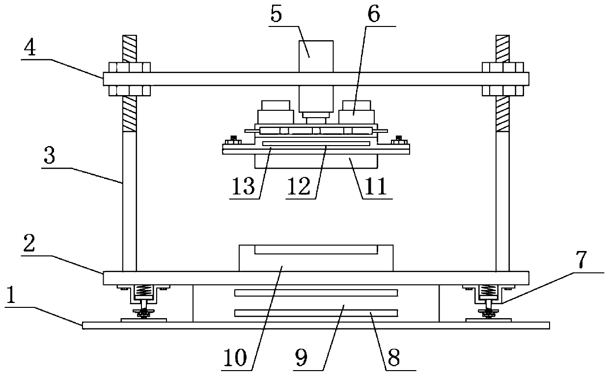
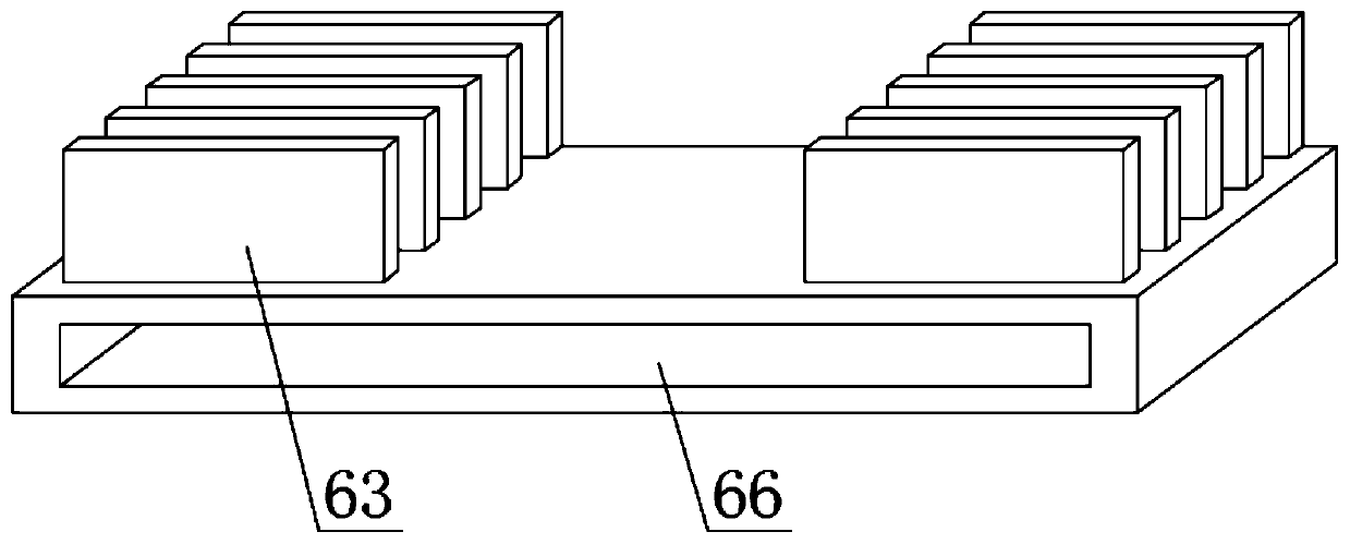
[0022] See Figure 1-Figure 4 , The present invention provides a technical solution: a sheet metal stamping device with good heat dissipation effect, comprising a second support plate 2, the upper surface of the second support plate 2 is provided with a downward pressing mold 10 in the middle of the upper surface of the second support plate 2 A third support plate 4 is provided. Both ends of the upper surface of the second support plate 2 are welded with support rods 3 corresponding to the third support plate 4, and the middle of the lower surface of the third support plate 4 is provided with a punching cylinder 5. 5 is provided with a heating base 13 underneath the heating base 13 is provided with an upper pressing mold 11 corresponding to the lower pressing mold 10, and the bottom end of the heating base 13 is provided with a heating coil 12 corresponding to the upper pressing mold 11. The bottom end of the cylinder 5 is provided with a heat dissipation mec...
Example Embodiment
[0026] Example 2:
[0027] On the basis of embodiment 1, in order to make the damping effect of the punching device better, in this embodiment, preferably, a first support plate 1 is provided below the second support plate 2, and the upper surface of the first support plate 1 A shock absorbing mechanism 7 corresponding to the second support plate 2 is provided at both ends. The shock absorbing mechanism 7 includes a limit base 74. The top end of the limit base 74 is welded to the second support plate 2. The limit base 74 is provided with The second limit plate 76, the second limit plate 76 can slide vertically along the limit base 74, the upper surface of the second limit plate 76 is provided with a shock-absorbing spring 75, and the fourth limit base 74 is provided below The support plate 72, the fourth support plate 72 is welded to the first support plate 1, and the middle of the upper surface of the fourth support plate 72 is provided with a limit rod 71 corresponding to the s...
Example Embodiment
[0032] Example 3:
[0033] On the basis of embodiment 2, in order to make the damping effect of the punching device better, in this embodiment, preferably, the upper surface of the first support plate 1 is provided with a damping plate 9 corresponding to the second support plate 2. , The damping plate 9 is a rectangular parallelepiped structure, the material of the damping plate 9 is rubber, and the damping plate 9 is connected to the first support plate 1 by glue;
[0034] In order to make the damping effect of the damping plate 9 better in this embodiment, preferably, a damping magnet 8 is embedded in the damping plate 9. The damping magnet 8 has a rectangular parallelepiped structure, and there are two damping magnets 8. , The magnetic poles of the opposite sides of the two shock-absorbing magnets 8 are the same;
[0035] When in use, the shock-absorbing plate 9 converts the received kinetic energy into its own elastic potential energy, thereby playing a shock-absorbing effect. A...
PUM
 Abstract
Description
Claims
Application Information
 - Generate Ideas
- Intellectual Property
- Life Sciences
- Materials
- Tech Scout
- Unparalleled Data Quality
- Higher Quality Content
- 60% Fewer Hallucinations
Browse by: Latest US Patents, China's latest patents, Technical Efficacy Thesaurus, Application Domain, Technology Topic, Popular Technical Reports.
© 2025 PatSnap. All rights reserved.Legal|Privacy policy|Modern Slavery Act Transparency Statement|Sitemap|About US| Contact US: help@patsnap.com


