
Cross coupling structure for adjusting symmetry of transmission zero points

A technology of transmission zero point and cross-coupling, which is applied in the direction of electrical components, circuits, waveguide devices, etc., to achieve the effect of flexible arrangement and improved design flexibility

Pending Publication Date: 2019-12-10
江西一创新材料有限公司
View PDF0 Cites 14 Cited by
  • Summary
  • Abstract
  • Description
  • Claims
  • Application Information

AI Technical Summary

Problems solved by technology

However, the previous dielectric filter coupling structure with symmetrical zero characteristics formed a fixed symmetrical zero arrangement, that is, the zero point at the high end of the filter passband is always closer to the passband than the zero point at the low end.

Method used


Image

  • Cross coupling structure for adjusting symmetry of transmission zero points
  • Cross coupling structure for adjusting symmetry of transmission zero points
  • Cross coupling structure for adjusting symmetry of transmission zero points

Examples


Embodiment 1

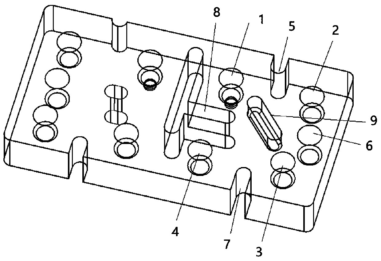
[0014] On the basis of the above solution, in an embodiment, the cross-coupling structure is used in an 8th-order dielectric filter to realize the adjustment of the symmetry of the transmission zero point.

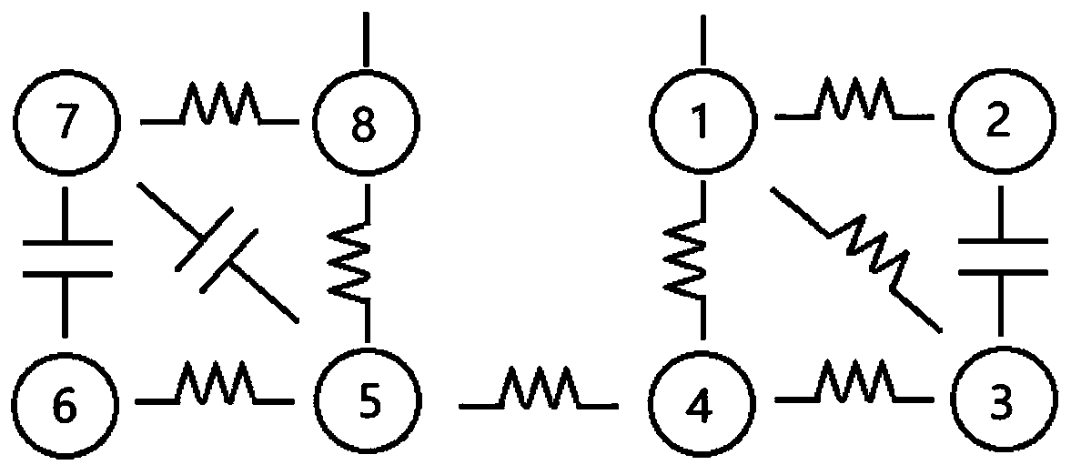
[0015] like figure 2 As shown, the 8th-order dielectric filter is composed of 8 blind hole resonators 10, 11...17 and coupling structures 18, 19...28 between them. Combined with its equivalent circuit image 3 As shown, the blind hole resonators 10, 11...17 correspond to the resonance units 1, 2...8 in the equivalent circuit, and the coupling window 18 between the blind hole resonators 10, 11 corresponds to the resonance in the equivalent circuit The inductive coupling between units 1 and 2 is similar. The coupling windows 20, 21, 22, 24, 25, and 28 are all inductive coupling, while the coupling holes 19, 23 are capacitive coupling.

[0016] like image 3 The first 4 resonant units 1, 2, 3, 4 shown form Figure 4 The symmetrical two transmission zeros 29, 30 shown in ...


PUM


Abstract

The invention relates to a cross coupling structure for adjusting the symmetry of transmission zero points, which is a blind slot and is used for realizing the coupling between two non-adjacent blindhole resonators, and the blind slot can be connected with any one or two of the two non-adjacent blind hole resonators and can also be not connected with any one or two of the two non-adjacent blind hole resonators to form an independent blind slot. After the blind groove is additionally arranged, the symmetry of the transmission zero points at two ends of the passband can be adjusted, the longerthe blind slot is, the transmission zero point at the lower end of the passband is closer to the passband than the transmission zero point at the higher end of the passband, and otherwise, the two transmission zero points tend to be symmetrical.

Description

technical field [0001] The invention relates to a cross-coupling structure for adjusting the symmetry of transmission zero point, which belongs to the technical field of electronic components in the field of communication. Background technique [0002] In recent years, with the increasing demand for high performance and miniaturization of communication equipment, dielectric filters have received more and more attention. However, in the previous dielectric filter coupling structure with symmetrical zero characteristics, the symmetrical zero arrangement characteristics formed are fixed, that is, the zeros at the high end of the filter passband are always closer to the passband than the zeros at the low end. Contents of the invention [0003] The present invention provides a cross-coupling structure for adjusting the symmetry of the transmission zero point, which can change the symmetry of the symmetrical zero point, that is, realize that the zero point at the low end of the ...

Claims


Application Information

Patent Timeline
Patent Type & Authority Applications(China)
IPC IPC(8): H01P1/20
CPCH01P1/2002
Inventor 何祥勇王一凡王平舒剑龙
Owner 江西一创新材料有限公司
Learn More