Electrolytic water hydrogen production electrolytic tank based on solar power generation

A technology of solar energy and electrolysis of water, which is applied in the field of electrolysis cells, can solve the problems of reducing electrolysis efficiency, affecting electrolysis, time-consuming and labor-intensive problems, and achieves the effects of improving electrolysis efficiency, reducing hydrogen production costs, and saving waste

Inactive Publication Date: 2019-12-10
北京八度阳光科技有限公司
View PDF0 Cites 2 Cited by
  • Summary
  • Abstract
  • Description
  • Claims
  • Application Information

AI Technical Summary

Problems solved by technology

[0003] When the current electrolytic cell electrolyzes water for a long time, the internal liquid will continue to decrease. During the electrolysis, it is necessary to manually increase the lye to the interior. The increase process is very time-consuming and laborious, and reduces the electrolysis efficiency. Generally, the solar panel is directly fixed and installed on the electrolytic cell for power generation and hydrogen production, which not only affects the electrolysis, but also fixes the installation of solar energy, making it difficult to track solar energy and meet sufficient electricity demand. Therefore, we propose a solar energy-based Electrolytic cell for hydrogen production by electrolysis of water for power generation

Method used


Image

  • Electrolytic water hydrogen production electrolytic tank based on solar power generation
  • Electrolytic water hydrogen production electrolytic tank based on solar power generation
  • Electrolytic water hydrogen production electrolytic tank based on solar power generation

Examples


Embodiment Construction

[0018] The following will clearly and completely describe the technical solutions in the embodiments of the present invention with reference to the accompanying drawings in the embodiments of the present invention. Obviously, the described embodiments are only some, not all, embodiments of the present invention. Based on the embodiments of the present invention, all other embodiments obtained by persons of ordinary skill in the art without making creative efforts belong to the protection scope of the present invention.

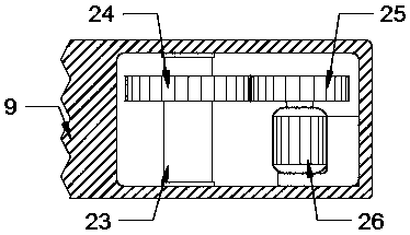
[0019] see Figure 1-3 , the present invention provides a technical solution: an electrolytic cell for producing hydrogen from electrolyzed water based on solar power generation, comprising a base 1 and a cell body 2, the top center of the base 1 is fixedly installed with the cell body 2, and the base 1 plays a supporting role. And the top of the base 1 is located on both sides of the pool body 2, and an oxygen storage tank 3 and a hydrogen storage tank 4 are ...


PUM


Abstract

The invention discloses an electrolytic water hydrogen production electrolytic tank based on solar power generation. The electrolytic water hydrogen production electrolytic tank includes a base and atank body, the tank body is fixedly installed at the center of the top of the base, an oxygen storage tank and a hydrogen storage tank are installed on both sides of the tank body at the top of the base correspondingly, a diaphragm is fixedly installed in the tank body, a storage box is fixedly installed at the center of the top of the tank body, a liquid inlet port is formed in one end of the topof the storage box, a power box is fixedly installed at the other end of the top of the storage box, the top of the power box is rotatably connected with a supporting plate, an electric push rod anda vertical rod are fixedly installed at both ends of the top of the supporting plate correspondingly, and the tops of the electric push rod and the vertical rod are rotatably connected with solar panels. According to the electrolytic tank, in the process of automatically adding liquid to the tank body, the situation that the time and labor are wasted and the consumed cost is high in previous manual material loading is avoided, the electrolytic efficiency is improved, electric power can be stored to the great extent, long-time electrolysis is convenient, waste of electric power resources is greatly saved, and the hydrogen production cost is lowered.

Description

technical field [0001] The invention relates to the technical field of electrolytic cells, in particular to an electrolytic cell for producing hydrogen by electrolyzing water based on solar power generation. Background technique [0002] Hydrogen production by electrolysis of water is an efficient and clean hydrogen production technology. The hydrogen production process is simple and the product purity is high. The purity of hydrogen and oxygen can generally reach 99.99%. At present, with the increasing power generation of renewable energy, hydrogen will become an ideal carrier for electric energy storage, and electrolysis of water to produce hydrogen requires the use of electrolytic cells. [0003] When the current electrolytic cell electrolyzes water for a long time, the internal liquid will continue to decrease. During the electrolysis, it is necessary to manually increase the lye to the interior. The increase process is very time-consuming and laborious, and reduces the ...

Claims


Application Information

Patent Timeline
IPC IPC(8): C25B9/04C25B9/08C25B15/08C25B1/10C25B9/19
CPCC25B15/08C25B1/04C25B9/73C25B9/65C25B9/19Y02E60/36Y02P20/133
Inventor 刘一锋
Owner 北京八度阳光科技有限公司
Why Eureka
Try Eureka