A straightening device for a spring machine

A straightening device and spring machine technology, applied in the field of spring machines, can solve problems affecting production efficiency, wire rod pressure loss, and wire straightening failure, so as to improve quality and straightness, ensure straightening, and improve quality Effect

Active Publication Date: 2021-03-16
苏州勇士自动化科技有限公司
View PDF7 Cites 0 Cited by
  • Summary
  • Abstract
  • Description
  • Claims
  • Application Information

AI Technical Summary

Problems solved by technology

[0003] 1. The existing straightening mechanism is to straighten the steel wire through the two sets of straightening wheels, and to straighten the steel wire through the pressure between the two sets of straightening wheels. For processing, it is necessary to debug the straightening mechanism before processing, and the existing debugging is manually fine-tuned for many times. Such an operation is time-consuming and laborious, and it will also affect the efficiency of production. Excessive pressure on the wire between the wheels will cause pressure loss on the wire. On the contrary, if the pressure is too small, the wire cannot be straightened well, which will affect the quality or straightness of the wire entering the forming mechanism. degree, will eventually affect the precision of spring processing
[0004] 2. The existing straightening mechanism only straightens the wire rod, and the force to drag the steel wire rod forward is still to pull out the steel wire rod on the mandrel by the pull pin on the chuck of the spring mandrel rod, thus producing The friction between the steel wire and the mandrel is realized, but when producing a spring with a relatively large rotation, because the friction between the steel wire and the mandrel is small, the power of the wire to advance during straightening cannot be realized, so the wire The straightening quality of the spring is greatly reduced, which will further affect the processing accuracy of the spring

Method used


Image

  • A straightening device for a spring machine
  • A straightening device for a spring machine
  • A straightening device for a spring machine

Examples


Embodiment Construction

[0018] The following will clearly and completely describe the technical solutions in the embodiments of the present invention with reference to the accompanying drawings in the embodiments of the present invention. Obviously, the described embodiments are only some, not all, embodiments of the present invention. Based on the embodiments of the present invention, all other embodiments obtained by persons of ordinary skill in the art without making creative efforts belong to the protection scope of the present invention.

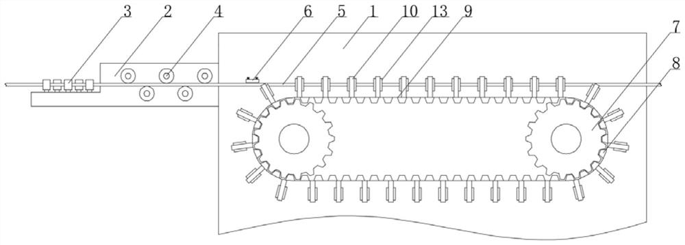
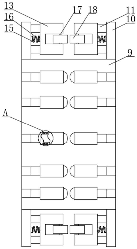
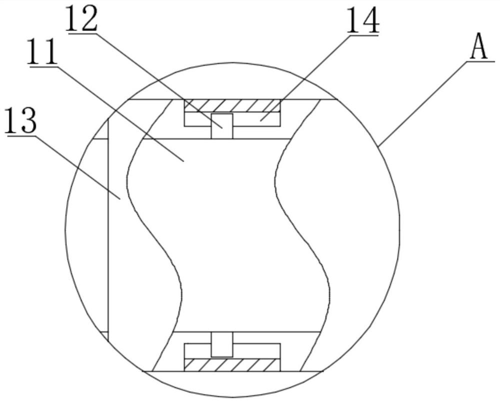
[0019] see Figure 1-3 , a straightening device of a spring machine, comprising a backboard 1, a feeding device 2 is fixedly installed on one side of the backboard 1, and a vertical feeding wheel 3 is fixedly installed on the upper surface of the feeding device 2 side, and the feeding device 2 The front of the other side is fixedly installed with a horizontal feed wheel 4, and the upper and lower horizontal feed wheels 4 are movably connected with a steel wire...


PUM


Abstract

The invention relates to the technical field of spring machines, and discloses a straightening device of a spring machine. The straightening device comprises a back plate; a material feeding device isfixedly arranged on one side of the back plate; a vertical material feeding wheel is fixedly arranged on the upper surface of one side of the material feeding device; according to the straightening device of the spring machine, a straightening spring is arranged on the middle parts of two opposite surfaces of each vertical rod and a corresponding U-shaped sleeve; each U-shaped sleeve movably sleeves a cross rod; a steel wire material is straightened by utilizing a pair of rotary wheels; identical mechanisms are arranged on two ends of the steel wire materials, so that the central position ofthe steel wire material cannot displace laterally; a traditional method of straightening the steel wire material through rigid press between two straightening wheels is replaced by a method of utilizing the straightening springs with high strength, so that a good straightening effect is realized for the wire material on the premise of not damaging the wire material; and besides, when wire materials of different diameters are straightened, subsequent spring machining precision can be ensured without repeatedly adjusting the distance between the straightening wheels.

Description

technical field [0001] The invention relates to the technical field of spring machines, in particular to a straightening device for a spring machine. Background technique [0002] A spring machine is a machine used to produce springs. It roughly includes five parts: a feeding mechanism, a straightening mechanism, a diameter-changing mechanism, a pitch changing mechanism and a cutting mechanism. The straightening mechanism is located between the feeding frame and the feeding roller. , which consists of two rows of straightening wheels. The purpose of straightening is to eliminate the original bending deformation of the steel wire, so that the wire can enter the forming mechanism straightly, which can ensure the processing accuracy of the spring, but the existing straightening mechanism still exists. Some flaws: [0003] 1. The existing straightening mechanism is to straighten the steel wire through the two sets of straightening wheels, and to straighten the steel wire throug...

Claims


Application Information

Patent Timeline
Patent Type & Authority Patents(China)
IPC IPC(8): B21F23/00B21F1/02B21F35/00
CPCB21F1/02B21F23/00B21F35/00
Inventor 刘榕副
Owner 苏州勇士自动化科技有限公司
Why Eureka
Try Eureka