
Multifunctional air fryer

An air fryer and multi-functional technology, applied in the field of kitchen appliances, can solve the problems of affecting the appearance, insufficient air intake, wrong plug insertion, etc., to improve the heat dissipation effect, improve the air intake efficiency, and ensure the effect of normal use.

Pending Publication Date: 2019-12-10
ZHEJIANG KELAND ELECTRIC APPLIANCE
View PDF0 Cites 1 Cited by
  • Summary
  • Abstract
  • Description
  • Claims
  • Application Information

AI Technical Summary

Problems solved by technology

The main defect of the existing scheme is that the air inlet is small, the air intake is not enough, the wind pressure is insufficient, the heat is driven less, the heat dissipation is not timely, and the heat is easy to accumulate and cannot be diffused. If the area of ​​​​the air inlet is increased, a certain amount of noise will be generated, and When the air fryer finishes working, the internal heat rises sharply and gathers on the underside of the top cover, which is not easy to spread, causing harm to the air fryer
[0004] Moreover, in the existing air fryer, the power cord is exposed outside the machine and cannot be stored. After the product is used, the power cord can only be placed on the workbench in the kitchen. There are two disadvantages in this structure: one is to affect the appearance; First, when multiple kitchen products are placed on the workbench, there is a risk of plugging in the wrong plug. Third, the connection strength of the interface of the power cord is not good. Experience
[0005] In addition, in the process of actually using the air fryer, when the user puts the back of the air fryer close to the wall, the temperature of the air fryer and the wall will rise too high, and there is a risk of fire

Method used


Image

  • Multifunctional air fryer
  • Multifunctional air fryer
  • Multifunctional air fryer

Examples


Embodiment Construction

[0037] Embodiments of the present invention will be described in detail below in conjunction with the accompanying drawings.

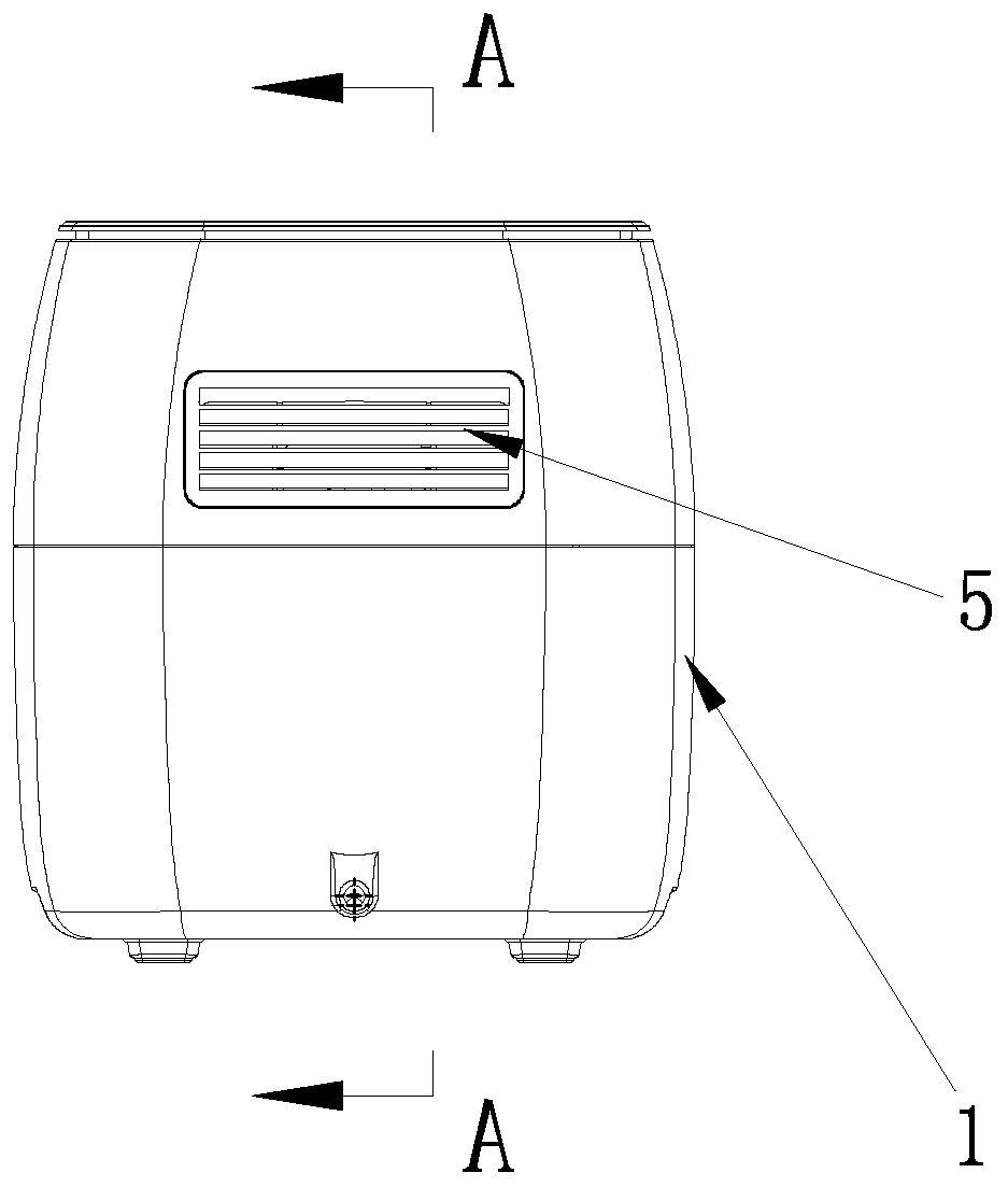
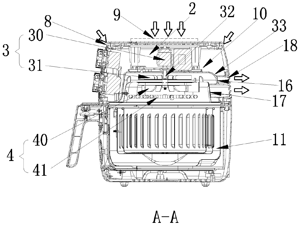
[0038] Example: such as Figure 1-4As shown, a heat dissipation device for an air fryer includes an outer shell 1, an inner shell 2, a cold air device 3 and a hot air device 4, the upper part of the rear side of the outer shell 1 is provided with an air outlet 5, and the inner shell 2 includes an upper cavity 10 and a lower cavity. In the cavity 11, the cold air device 3 is located in the upper cavity 10 and close to the center of the upper cavity 10. The hot air device 4 is located below the upper cavity 10 and above the lower cavity 11. The air guide hood 16 separates the device 3 from the hot air device 4; the hot air generated by the hot air device 4 flows directly downward into the fryer, which reduces the flow path of the hot air and prevents the hot air temperature from dropping rapidly, thereby improving the heating efficiency, thereby improvin...


PUM


Abstract

The invention relates to a multifunctional air fryer. The multifunctional air fryer comprises a shell, an inner shell, a cold air device and a hot air device, wherein an air outlet is formed in the upper part of the rear side of the shell; the inner shell comprises an upper cavity and a lower cavity; the cold air device is positioned in the upper cavity and close to the center of the upper cavity;the hot air device is positioned under the upper cavity and positioned on the lower cavity; and an air director for separating the cold air device from the hot air device is arranged under the uppercavity; a top cover is arranged on the top of the shell, and the top cover is provided with a cold air inlet device communicating with the cold air device; and the cold air inlet device comprises an annular air inlet and a top air inlet. The top cover is provided with the cold air inlet communicating with the cold air device, so that external cold air can directly enter the upper cavity to be driven by the cold air device, to cool each element in the upper cavity.

Description

technical field [0001] The invention belongs to the technical field of kitchen appliances, and in particular relates to a multifunctional air fryer. Background technique [0002] With the development of science and technology and the improvement of the quality of life of the public, people pay more and more attention to video health. The appearance of the air fryer has solved to a certain extent the food health problems caused by the cooking of food with oil in traditional cooking equipment. The air fryer is used The high-speed air circulation technology makes the cooking effect reach the effect and taste of fried food, that is, high-temperature hot air is generated in the pot to form a crispy surface layer on the surface of the food, lock the moisture inside the food, and achieve the taste of ordinary fried food. [0003] The existing air fryer cold air system generally adopts the air intake around the top cover, and there is a certain air intake gap around the top cover an...

Claims


Application Information

Patent Timeline
IPC IPC(8): A47J37/06
CPCA47J37/0629A47J37/0641A47J37/0664
Inventor 汪书明王强
Owner ZHEJIANG KELAND ELECTRIC APPLIANCE
Learn More