
Diagonal flow fans and home appliances

A technology of oblique flow fan and oblique flow fan, which is applied in mechanical equipment, machine/engine, liquid fuel engine, etc., can solve the problems of unstable operation of oblique flow fan, large differential pressure, and fluctuation of flow field inside the impeller.

Active Publication Date: 2021-03-02
MIDEA GRP CO LTD
View PDF7 Cites 0 Cited by
  • Summary
  • Abstract
  • Description
  • Claims
  • Application Information

AI Technical Summary

Problems solved by technology

[0004] Under the condition of small flow rate, due to the large differential pressure between the pressure surface and the suction surface of the impeller, a strong blade tip leakage vortex appears under the combined action of the differential pressure on both sides and the underflow, forming a large number of vortices on the blade tip. However, when the flow rate of the diagonal flow fan is reduced to a certain extent, a large area of ​​backflow area can be observed in the blade tip area. At this time, the internal flow field of the impeller fluctuates, resulting in unstable operation of the diagonal flow fan in the application. In the case of a small pressure fluctuation, the flow rate fluctuates greatly, which has a great impact on the aerodynamic performance and noise performance of the diagonal flow fan, and the low-energy fluid then enters the diffuser and interferes with the diffuser blades. also resulted in increased leaf octave noise while stalling

Method used


Image

  • Diagonal flow fans and home appliances
  • Diagonal flow fans and home appliances
  • Diagonal flow fans and home appliances

Examples


Embodiment Construction

[0043] In order to understand the above-mentioned purpose, features and advantages of the present invention more clearly, the present invention will be further described in detail below in conjunction with the accompanying drawings and specific embodiments. It should be noted that, in the case of no conflict, the embodiments of the present application and the features in the embodiments can be combined with each other.

[0044] In the following description, many specific details are set forth in order to fully understand the present invention. However, the present invention can also be implemented in other ways different from those described here. Therefore, the protection scope of the present invention is not limited by the specific details disclosed below. EXAMPLE LIMITATIONS.

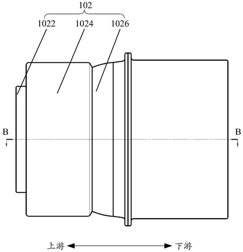
[0045] Refer below Figure 3 to Figure 5 Diagonal flow fans according to some embodiments of the present invention are described.

[0046] Such as image 3 and Figure 4 As shown, the oblique flo...


PUM


Abstract

The present invention proposes a diagonal flow fan and household appliances, wherein the diagonal flow fan includes: a wheel cover assembly, including a plurality of set wheel covers, the wheel cover is provided with an air inlet, and any two adjacent wheel covers are in The outer wheel cover extends downstream relative to the inner wheel cover so as to A return flow channel is formed between the two wheel covers, and the return flow channel is connected with the air inlet; the diagonal flow fan is partially disposed inside the innermost wheel cover among the plurality of wheel covers, and the diagonal flow fan includes a wheel hub and a plurality of wheels arranged on the wheel hub. The blade and the top of the blade can be arranged corresponding to the entrance of the return channel. Through the technical solution of the present invention, the stability of the operation of the diagonal flow fan is improved, the aerodynamic performance of the diagonal flow fan is improved, and the probability of an increase in blade frequency multiplication noise is reduced.

Description

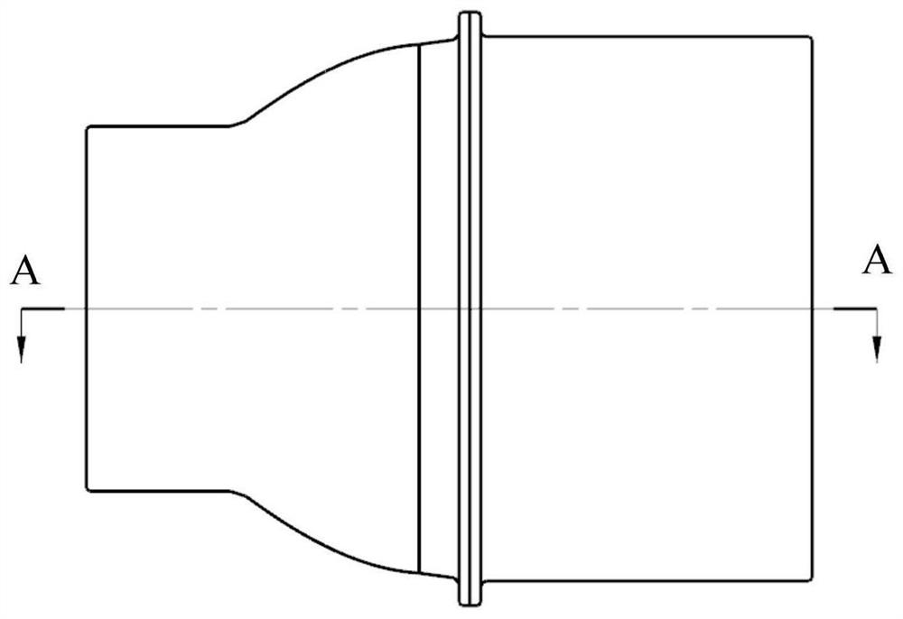
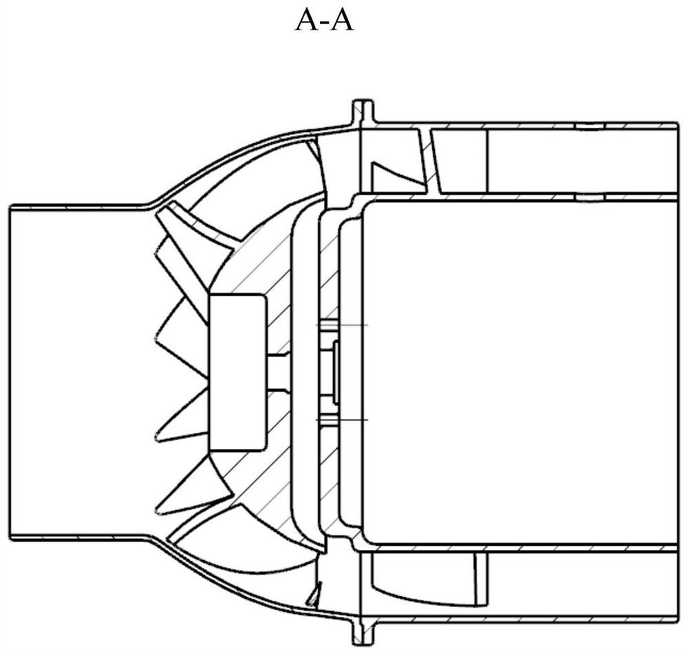
technical field [0001] The invention relates to the field of home appliances, in particular to a diagonal flow fan and a home appliance. Background technique [0002] Diagonal flow fan, also known as mixed flow fan, is a type of fan between centrifugal fan and axial flow fan. This type of fan has the characteristics of higher exhaust pressure than axial flow fan and higher efficiency than centrifugal fan. It has become more and more popular in recent years. It has been applied more and more. In related technologies, the structure of the diagonal flow fan is as follows figure 1 and figure 2 As shown, the following defects still exist during operation: [0003] Under the working conditions with a relatively wide range of flow rates, flow separation or even backflow is prone to occur at the top of the blades of the oblique flow fan near the outlet, resulting in a wider stall zone for the oblique flow fan, which is shown as axial flow on the performance curve. The flow fan i...

Claims


Application Information

Patent Timeline
Patent Type & Authority Patents(China)
IPC IPC(8): F04D29/26F04D29/40F04D29/66
CPCF04D29/26F04D29/403F04D29/661F04D29/666
Inventor 胡小文张辉
Owner MIDEA GRP CO LTD
Learn More