
A High Resolution Minimum Variance Ultrasound Imaging Method Based on Frequency Domain Segmentation

An ultrasonic imaging method and a technique of minimum variance, which are applied to the analysis of fluids using sound waves/ultrasonic waves/infrasonic waves, the analysis of solids using sound waves/ultrasonic waves/infrasonic waves, and the use of sound waves/ultrasonic waves/infrasonic waves for material analysis, etc., to improve the robustness of the algorithm and improve Imaging efficiency, the effect of improving algorithm efficiency

Active Publication Date: 2021-10-08
CHONGQING UNIV +3
View PDF0 Cites 0 Cited by
  • Summary
  • Abstract
  • Description
  • Claims
  • Application Information

AI Technical Summary

Problems solved by technology

[0006] In view of this, the object of the present invention is to provide a high-resolution minimum variance ultrasonic imaging method based on frequency domain segmentation, which can significantly improve the imaging resolution and contrast of the algorithm, and simultaneously improve the algorithm efficiency and beamforming robustness , effectively overcome the contradictory problem that the broadband and strongly correlated ultrasonic echo signals do not meet the narrow-band and non-correlated application conditions of the traditional minimum variance adaptive beamforming algorithm, thus comprehensively improving the quality of ultrasonic imaging

Method used


Image

  • A High Resolution Minimum Variance Ultrasound Imaging Method Based on Frequency Domain Segmentation
  • A High Resolution Minimum Variance Ultrasound Imaging Method Based on Frequency Domain Segmentation
  • A High Resolution Minimum Variance Ultrasound Imaging Method Based on Frequency Domain Segmentation

Examples


Embodiment Construction

[0073] The preferred embodiments of the present invention will be described in detail below with reference to the accompanying drawings.

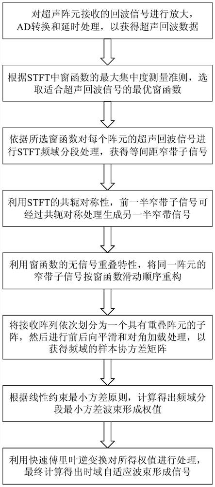
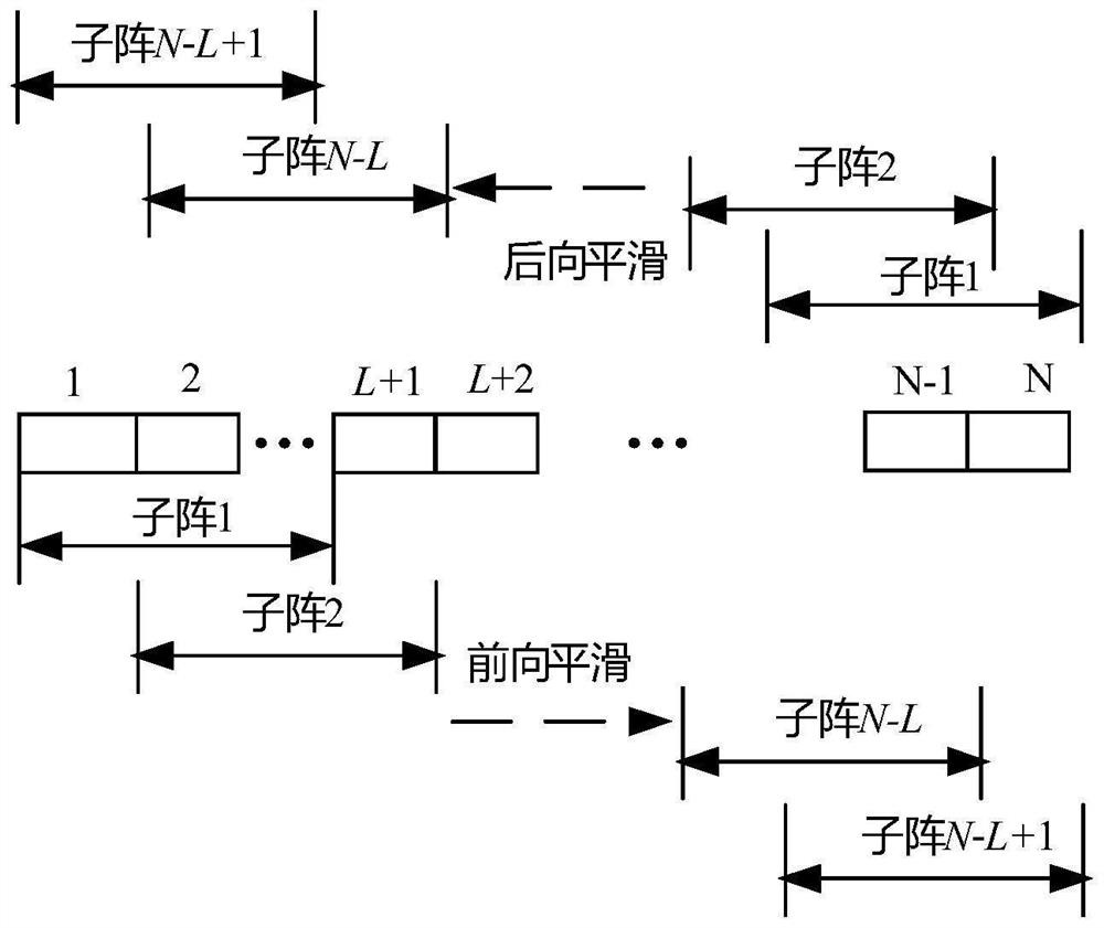
[0074] figure 1 It is a flowchart of the method of the present invention, figure 2 It is a schematic diagram of forward and backward spatial smoothing algorithm. As shown in the figure, the present invention provides a high-resolution minimum variance ultrasonic imaging method based on time-frequency segmentation, which specifically includes the following steps:

[0075] Step S1: Perform amplification, AD conversion and delay processing on the echo signal received by the ultrasonic array element to obtain ultrasonic echo data; obtain the signal x(τ)=[x 1 (τ),x 2 (τ),...x N (τ)], x 1 (τ)...x N (τ) respectively represent the echo signals received by each array element, N represents the number of ultrasonic array elements, and τ represents the sampling time corresponding to the depth;

[0076] Step S2: According to the maximum concentra...


PUM


Abstract

The invention relates to a high-resolution minimum variance ultrasonic imaging method based on frequency domain segmentation, belonging to the field of ultrasonic imaging. In this method, firstly, the sampling signal received by the array element is delayed to obtain the echo data required for ultrasonic focusing; secondly, according to the maximum concentration measurement criterion of the self-adaptive window function in STFT, the optimal window function of the frequency domain segment is selected; STFT converts the ultrasonic echo signal into a narrow-band sub-signal; using conjugate symmetry, the first half of the narrow-band sub-signal is processed by conjugate symmetry to generate the other half of the narrow-band signal; the receiving array is sequentially divided into sub-arrays with overlapping elements, and the frequency Domain signals are processed by forward and backward smoothing and diagonal loading to obtain the sample covariance matrix; finally, the frequency domain segmental minimum variance beamforming weights are processed by inverse fast Fourier transform to obtain the final time domain adaptive beamforming signal . The method can significantly improve the resolution of ultrasound imaging, increase the contrast, and can improve the quality of ultrasound imaging as a whole.

Description

technical field [0001] The invention belongs to the technical field of ultrasonic imaging, and relates to a high-resolution minimum variance ultrasonic imaging method based on frequency domain segmentation. Background technique [0002] Ultrasonic imaging is widely used in the field of nondestructive testing and diagnosis due to its advantages of safety, non-invasiveness, real-time and low cost. Beamforming technology is the key technology of ultrasonic imaging, which directly determines the image quality of ultrasonic imaging. Delay And Sum (DAS) is the most widely used and simplest beamforming technique in ultrasound imaging. It calculates the delay amount of the received echo signal according to the geometric position relationship of the array element channel, and then aligns and superimposes the delayed data. The traditional DAS algorithm has low complexity, good robustness, and fast imaging speed, but because it uses a fixed window function weighting to increase the wi...

Claims


Application Information

Patent Timeline
Patent Type & Authority Patents(China)
IPC IPC(8): G01N29/04G01N29/02G01N29/06G01N29/44G06F17/15
CPCG01N29/02G01N29/04G01N29/0654G01N29/4454G01N2291/044G06F17/15
Inventor 王平杜婷婷王林泓孔露李锡涛柳学功孔美娅田训梁家祺王慧悦
Owner CHONGQING UNIV
Learn More