
Communication equipment mounting bracket

A technology for installing brackets and communication equipment, which is applied in the direction of telephone communication, branch office equipment, telephone structure, etc. It can solve the problems of no anti-drop pad, the inability to enhance the sound of incoming calls, and unfavorable use by users, so as to achieve a scientific and reasonable structure. It is safe and convenient to use and the effect of improving the quality of use

Inactive Publication Date: 2019-11-22
陕西云彩信息科技有限公司
View PDF0 Cites 2 Cited by
  • Summary
  • Abstract
  • Description
  • Claims
  • Application Information

AI Technical Summary

Problems solved by technology

[0004] The present invention provides a mounting bracket for communication equipment, which can effectively solve the problems mentioned above in the background technology that there is no loudspeaker, the sound of the incoming call cannot be enhanced, and the information reminder to the user is affected, and the communication terminal cannot be prevented from The collision of the main body affects the quality of use of the communication terminal body. There is no storage card slot, the communication content cannot be recorded at any time, and useful communication information cannot be saved for the user. There is no lifting rod and turntable, and the position and position of the communication terminal body cannot be adjusted at any time. Rotating the direction of the communication terminal body is not conducive to the use of the user

Method used


Image

  • Communication equipment mounting bracket
  • Communication equipment mounting bracket
  • Communication equipment mounting bracket

Examples


Embodiment

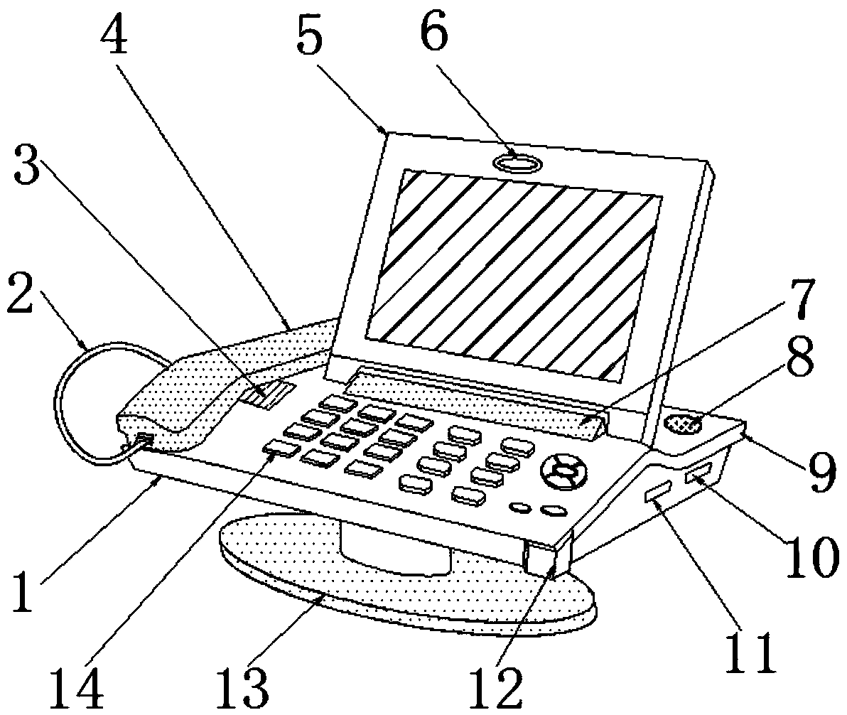
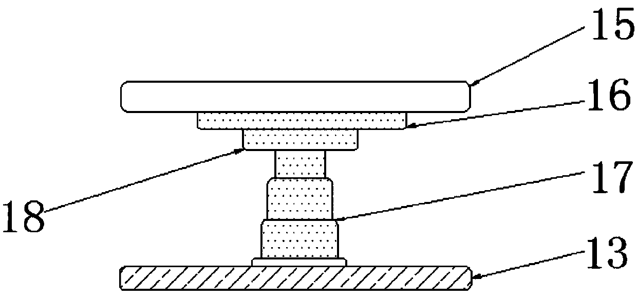
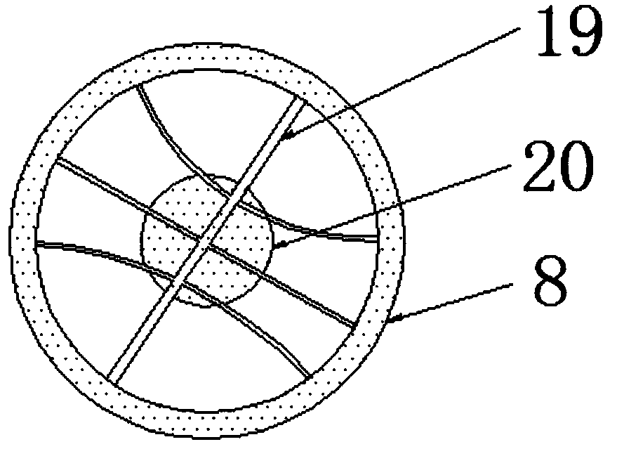
[0018] Example: such as Figure 1-3 As shown, the present invention provides a technical solution, a communication equipment mounting bracket, including a communication terminal body 1, a connecting line 2, a speaker 3, a microphone 4, a display screen 5, a camera 6, a hinge 7, a loudspeaker 8, Telephone base 9, communication interface 10, storage card slot 11, anti-drop pad 12, base 13, buttons 14, turntable 15, bearing 16, lifting rod 17, rotating shaft 18, voice coil 19 and diaphragm 20, communication terminal body 1 The upper end is provided with a microphone 4, and the upper end of the communication terminal body 1 is provided with a display screen 5 at a position close to the side of the microphone 4, the upper surface of the communication terminal body 1 is embedded with a speaker 3, and the upper surface of the communication terminal body 1 is close to the speaker 3 is provided with a button 14, the upper surface of the voice coil 19 is embedded with a loudspeaker 8 at...


PUM

PropertyMeasurementUnit
Thicknessaaaaaaaaaa

Abstract

The invention discloses a communication equipment mounting bracket. The communication equipment mounting bracket comprises a communication terminal body, a loudspeaker, an anti-falling pad, a rotatingdisc and a lifting rod, the loudspeaker is embedded in the position, close to one side of a display screen, of the upper surface of a voice coil, the anti-falling pad wraps one end of a telephone base, a storage clamping groove is formed in one side of the telephone base, and the rotating disc is arranged at the upper end of the base. The structure is scientific and reasonable, and safe and convenient in use; the loudspeaker is disposed, and then the size of incoming call sound can be increased; the anti-falling pad is disposed, and then the problem that the service life of the communicationterminal body is influenced by collision of the communication terminal body is avoided; the storage clamping groove is disposed, communication content can be recorded at any time, and a user can storeuseful information conveniently; the lifting rod and the rotating disc are arranged, the position of the communication terminal body and the direction of the rotary communication terminal body can beadjusted at any time; and the design is simple in structure, practical in function and beneficial to operation of the user.

Description

technical field [0001] The invention relates to the technical field of intelligent communication terminals, in particular to a communication equipment installation bracket. Background technique [0002] Intelligent communication terminal is a direct tool for people to enjoy different information applications. It undertakes various tasks such as providing users with a good user interface, completing required business functions, and accessing communication networks. Intelligent communication terminals include audio, image, video and several types of communication terminals for data. [0003] However, the intelligent communication terminals currently on the market are not only complex in structure, but also have single functions. Without a loudspeaker, the sound of the incoming call cannot be enhanced, which affects the information reminder sent to the user. bumps, affecting the quality of use of the communication terminal body, no storage card slot is set, communication conte...

Claims


Application Information

Patent Timeline
IPC IPC(8): H04M1/62H04M1/18H04M1/12H04M1/02
CPCH04M1/0295H04M1/12H04M1/185H04M1/62
Inventor 陈高飞
Owner 陕西云彩信息科技有限公司
Learn More