A configuration optimization method for reactive power compensation in power system

A power system and configuration optimization technology, applied in reactive power compensation, reactive power adjustment/elimination/compensation, circuit devices, etc., to achieve the effects of improving efficiency, reducing the scope and number of configurations, and shrinking the system node network

Inactive Publication Date: 2020-10-27
TSINGHUA UNIV +2
View PDF5 Cites 0 Cited by
  • Summary
  • Abstract
  • Description
  • Claims
  • Application Information

AI Technical Summary

Problems solved by technology

On the one hand, this method aggregates the candidate nodes through the initial screening of the load rate, and uses the nodes with strong interaction among the candidate nodes of the multi-infeed interaction factor (MIIF) to aggregate, and at the same time, considers the reactive voltage source—the generator and the MIIF phase The role of combination, select a node with the strongest interaction with other nodes in the aggregation as a candidate node, shrink the system node network, and improve the efficiency of candidate node selection; In order to solve the reactive power optimization problem of AC / DC transmission system (voltage stability problem) provides an effective method

Method used


Image

  • A configuration optimization method for reactive power compensation in power system
  • A configuration optimization method for reactive power compensation in power system
  • A configuration optimization method for reactive power compensation in power system

Examples


Embodiment Construction

[0053] An electric power system reactive power compensation configuration optimization method proposed by the present invention will be further described in detail below in conjunction with the accompanying drawings and specific embodiments.

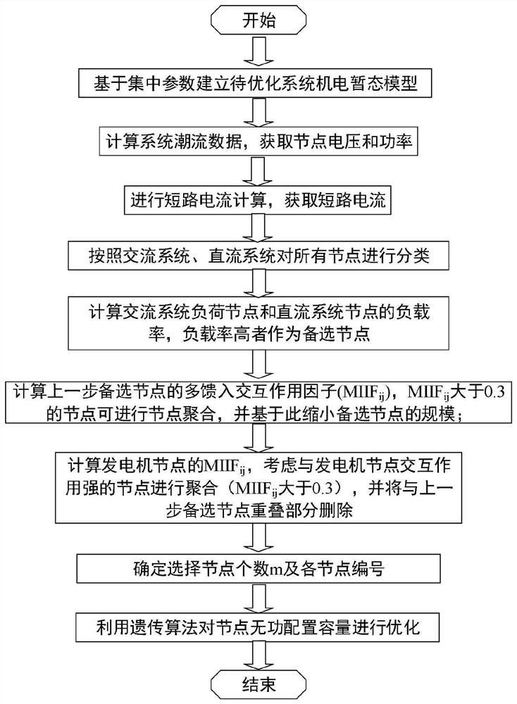
[0054] A method for optimizing reactive power compensation configuration of a power system proposed by the present invention, the overall process is as follows figure 1 shown, including the following steps:

[0055] 1) Based on the electromechanical transient simulation program (such as BPA, etc.), the lumped parameter model is used to establish the electromechanical transient simulation model of the power system to be optimized;

[0056] 2) Through the electromechanical transient program, perform power flow calculation and short-circuit current calculation on the simulation model established in step 1), and obtain the power flow data of each node in the power system to be optimized, including: the real part of the voltage e of each node...


PUM


Abstract

The invention provides a reactive power compensation configuration optimization method for a power system, and belongs to the field of reactive power compensation configuration of the power system. The method comprises the following steps: firstly, establishing an electromechanical transient simulation model of a to-be-optimized power system, and acquiring power flow data and short-circuit currentof each node in the to-be-optimized power system; after the nodes are classified, with consideration of a node load rate, obtaining an initial alternative node configured with reactive compensation,and with consideration of the effect of a reactive voltage source and a multi-infeed interaction factor, performing aggregation to finally obtain a reactive compensation alternative node of the to-be-optimized power system; and optimizing the reactive power capacity required to be configured for each reactive power compensation alternative node by adopting a genetic algorithm to obtain a reactivepower capacity optimization compensation result of each reactive power compensation alternative node. The method is easy to implement and high in accuracy, and is a practical reactive compensation configuration optimization method for the power system.

Description

technical field [0001] The invention relates to an optimization method for reactive power compensation configuration of a power system, and belongs to the field of reactive power compensation configuration of a power system. Background technique [0002] Due to the uneven distribution of resources and unbalanced regional development, after a period of time, after the development of cross-regional AC and DC transmission, more load areas with multiple DC drop points have been formed. In the AC-DC power transmission system, the AC-DC converter whose topology is constantly changing, whether it is rectification or inverter operation, has become a nonlinear load of the AC system because it consumes a large amount of reactive power. That is, for the AC system, the DC transmission system is a reactive load. However, the non-recovery or continuous reduction of the AC system voltage may cause multiple commutation failures or even blockages in the multi-circuit DC transmission system....

Claims


Application Information

Patent Timeline
Patent Type & Authority Patents(China)
IPC IPC(8): H02J3/18
CPCH02J3/18H02J3/1871Y02E40/30
Inventor 唐绍普张树卿刘栋朱琳窦豪翔
Owner TSINGHUA UNIV
Why Eureka
Try Eureka