Electromagnetic transient modeling and calculating method for power grid comprising multi-voltage-source converter

A technology of voltage source type and calculation method, applied in computing, instrumentation, electrical digital data processing, etc., can solve the problems of increasing the amount of simulation calculation, large amount of network equation solving, and low simulation efficiency.

Active Publication Date: 2019-11-22
TSINGHUA UNIV
View PDF8 Cites 3 Cited by
  • Summary
  • Abstract
  • Description
  • Claims
  • Application Information

AI Technical Summary

Problems solved by technology

The second solution is to establish the ideal switching model of the switching device and the variable topology network equation model that retains the topology of the main circuit of the converter under the premise of ignoring the dynamic process of the switching moment of the device. Low; in order to improve simulation efficiency or realize real-time simulation, multiple converters are divided and decoupled through cables, and subnets containing mutually decoupled converters are solved in parallel. However, in order to realize decoupling between converters , the overall simulation may need to use a very small simulation step size (less than 5 microseconds) to achieve decoupling through the cable. Segmentation, the former significantly increases the amount of simulation calculations, the latter cannot guarantee the consistent convergence of the entire network solution, reduces the accuracy of simulation, and even causes simulation failure

Method used


Image

  • Electromagnetic transient modeling and calculating method for power grid comprising multi-voltage-source converter
  • Electromagnetic transient modeling and calculating method for power grid comprising multi-voltage-source converter
  • Electromagnetic transient modeling and calculating method for power grid comprising multi-voltage-source converter

Examples


Embodiment Construction

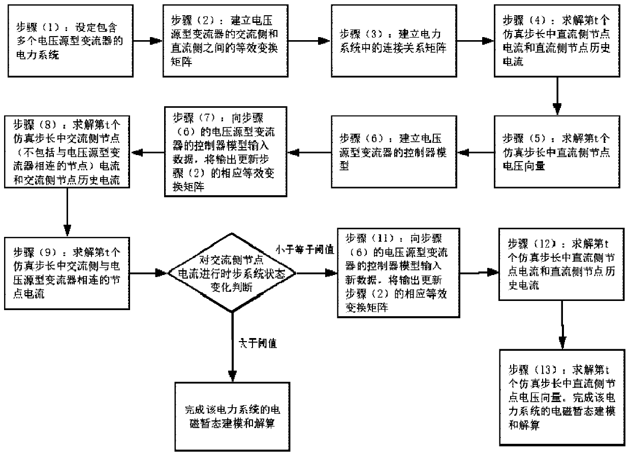
[0074] The electromagnetic transient modeling and calculation method of the power grid including multiple voltage source converters proposed by the present invention, its flow chart is as follows figure 1 Shown, it is characterized in that the method comprises the following steps:

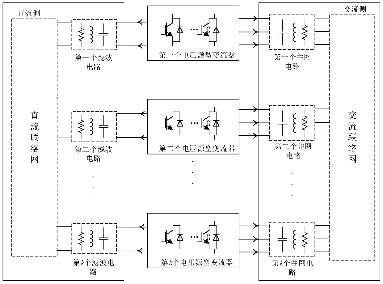
[0075] (1) Set up a power grid containing multiple voltage source converters, the structure of which is as follows figure 2 As shown, it consists of a DC side, an AC side and k voltage source converters, the DC side is composed of a DC connection network and k filter circuits, and the DC connection network is connected to k filter circuits respectively. The k filter circuits are respectively connected to the DC terminals of the k voltage source converters; the AC side is composed of k grid-connected circuits and an AC network, and the AC network is connected to the k grid-connected circuits respectively. The k grid-connected circuits of are respectively connected to the AC terminals of the k volt...


PUM


Abstract

The invention relates to an electromagnetic transient modeling and calculating method for a power grid containing a multi-voltage-source converter, and belongs to the technical field of dynamic simulation of power systems, microgrids and multiple power electronics. According to the method, converter switching device trigger control and switching action processes are considered, the original topology of a converter main circuit is reserved, and converter bottom layer control, switching transient and connection coupling lines and networks between converters can be accurately simulated. Accordingto the method, segmentation processing is not carried out. The coupling of the converters on the direct-current side and the alternating-current side is completely reserved. The consistent convergence of multi-converter networking whole-system solution is guaranteed. Errors caused by approximate decoupling or artificial network segmentation are eliminated. The method is suitable for electromagnetic transient process simulation of grid connection and networking of multiple power electronic converters, such as efficient simulation and real-time simulation of detailed electromagnetic transient processes of new energy grid connection, a direct-current power grid, a flexible direct-current back-to-back near-end power grid, a microgrid containing a distributed power supply and a shipboard airborne microgrid.

Description

technical field [0001] The invention relates to an electromagnetic transient modeling and calculation method for a power grid including multi-voltage source converters, and belongs to the technical field of power systems, micro-grids, and multi-power electronic dynamic simulation. Background technique [0002] Because power electronic equipment has many advantages such as small size, low price, fast response speed, and ability to achieve precise control, it has been widely used in all aspects of power systems such as power generation, transmission, distribution, and use. A large number of power electronic converters have been invested in modern power grids, and the trend of power electronics in power grids is accelerating, such as wind power, photovoltaics and other new energy sources connected to the grid, high-voltage direct current transmission and large-capacity power electronic compensation devices, medium and low-voltage direct current transmission and distribution netw...

Claims


Application Information

Patent Timeline
IPC IPC(8): G06F17/50G06Q50/06
CPCG06Q50/06
Inventor 张树卿于思奇王启航张东辉唐绍普
Owner TSINGHUA UNIV
Why Eureka
Try Eureka