
Continuous drying device used for production of silicon wafers and capable of automatically feeding and discharging

A technology of automatic loading and unloading, drying device, applied in the direction of drying, drying machine, drying gas arrangement, etc., can solve the problems of reducing the drying efficiency of silicon wafers, unable to automatically load and unload, affecting the processing of silicon wafers, etc. The effect of improving the drying effect and increasing the contact area

Inactive Publication Date: 2019-11-22
马鞍山致青工业设计有限公司
View PDF9 Cites 6 Cited by
  • Summary
  • Abstract
  • Description
  • Claims
  • Application Information

AI Technical Summary

Problems solved by technology

[0004] The purpose of the present invention is to provide a continuous drying device that can automatically load and unload materials for the production of silicon wafers, so as to solve the problem in the above-mentioned background technology that the drying of silicon wafers in the production of silicon wafers needs to be manually dispersed in the drying equipment. After the drying is finished, it will be taken out manually, the material cannot be loaded and unloaded automatically, the labor intensity is high, and continuous production cannot be performed, which reduces the drying efficiency of silicon wafers. At the same time, the drying effect is poor, which affects the processing of the next process of silicon wafers. The problem

Method used


Image

  • Continuous drying device used for production of silicon wafers and capable of automatically feeding and discharging
  • Continuous drying device used for production of silicon wafers and capable of automatically feeding and discharging
  • Continuous drying device used for production of silicon wafers and capable of automatically feeding and discharging

Examples


Embodiment Construction

[0032] The technical solutions in the embodiments of the present invention will be clearly and completely described below with reference to the accompanying drawings in the embodiments of the present invention. Obviously, the described embodiments are only a part of the embodiments of the present invention, but not all of the embodiments. Based on the embodiments of the present invention, all other embodiments obtained by those of ordinary skill in the art without creative efforts shall fall within the protection scope of the present invention.

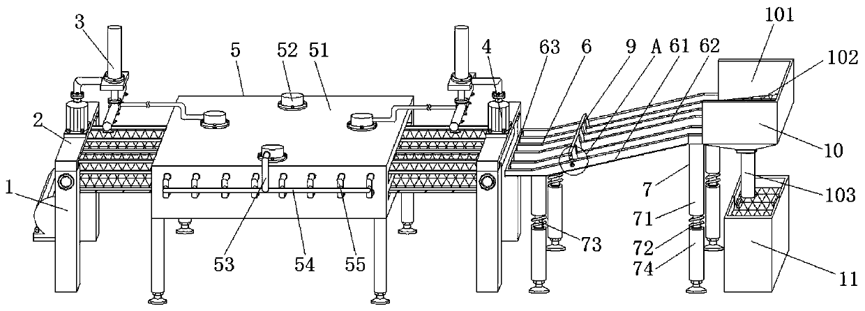
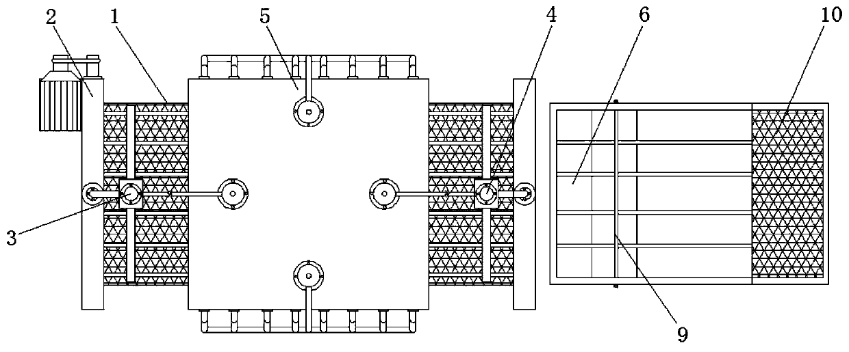
[0033] see Figure 1-10 , the present invention provides a technical solution: a continuous drying device for silicon wafer production that can be automatically loaded and unloaded, comprising a conveying mechanism 1, the upper end of the conveying mechanism 1 is fixedly connected with a support plate 2, and the support plate 2 at the left end of the conveying mechanism 1 A feeding mechanism 3 is fixedly connected to the upper end of ...


PUM


Abstract

The invention discloses a continuous drying device used for the production of silicon wafers and capable of automatically feeding and discharging. The continuous drying device comprises a conveying mechanism, the upper end of the conveying mechanism is fixedly connected with support plates; the upper end of the support plate at the left end of the conveying mechanism is fixedly connected with a discharging mechanism; the upper end of the support plate at the right end of the conveying mechanism is fixedly connected with a feeding mechanism; a drying mechanism is mounted between the dischargingmechanism and the feeding mechanism; a guiding mechanism is mounted at the right end of the conveying mechanism; the lower end of the guiding mechanism is fixedly connected with support columns and avibrating motor which is located between the support columns; a quantifying mechanism is mounted at the left end of the guiding mechanism; the right end of the guiding mechanism is fixedly connectedwith a receiving mechanism; and a water purifying mechanism is positioned at the lower end of the receiving mechanism. The continuous drying device used for the production of the silicon wafers and capable of automatically feeding and discharging, achieves not only continuous feeding and discharging in the production process but also continuous production, thereby not only reducing the labor intensity but also increasing the production efficiency.

Description

technical field [0001] The invention relates to the technical field of silicon wafer processing equipment, in particular to a continuous drying device capable of automatic loading and unloading for silicon wafer production. Background technique [0002] Silicon wafer is a crystal with a basically complete lattice structure, and different directions have different properties. It is a good semiconductor material and is involved in many fields. The production of silicon wafers needs to go through processes such as cutting, edging, heat treatment, cleaning, drying, and testing. During the drying process, drying equipment is required to be used together. [0003] However, for the drying of silicon wafers in the production of silicon wafers, it is necessary to manually disperse the silicon wafers in drying equipment for drying. After drying, they are manually taken out, which cannot be automatically loaded and unloaded, and the labor intensity is high and cannot be continuous. pr...

Claims


Application Information

Patent Timeline
IPC IPC(8): F26B15/18F26B21/00F26B25/00F26B25/02B01D46/00
CPCB01D46/00F26B15/18F26B21/001F26B25/00F26B25/02
Inventor 王玉庆胡苏安
Owner 马鞍山致青工业设计有限公司
Learn More