
Engine with working condition capable of switching miller cycle logic

A Miller cycle and engine technology, which is applied to engine components, engine control, combustion engines, etc., can solve the problems of switching control difficulties and affecting engine power, and achieve the effects of good load response, increased power, and improved efficiency

Pending Publication Date: 2019-11-22
ENTROPY ZERO TECH LOGIC ENG GRP CO LTD
View PDF6 Cites 0 Cited by
  • Summary
  • Abstract
  • Description
  • Claims
  • Application Information

AI Technical Summary

Problems solved by technology

[0002] The Miller cycle is of great significance for improving the efficiency of the engine, but it will affect the power of the engine. The logic of the Miller cycle is to reduce the amount of intake air while expanding the work volume. The logic with this cycle is called the Miller cycle logic. , since the real Miller cycle is realized by adjusting the closing time of the intake valve, it is difficult to switch and control in this way

Method used


Image

  • Engine with working condition capable of switching miller cycle logic
  • Engine with working condition capable of switching miller cycle logic
  • Engine with working condition capable of switching miller cycle logic

Examples


Embodiment 1

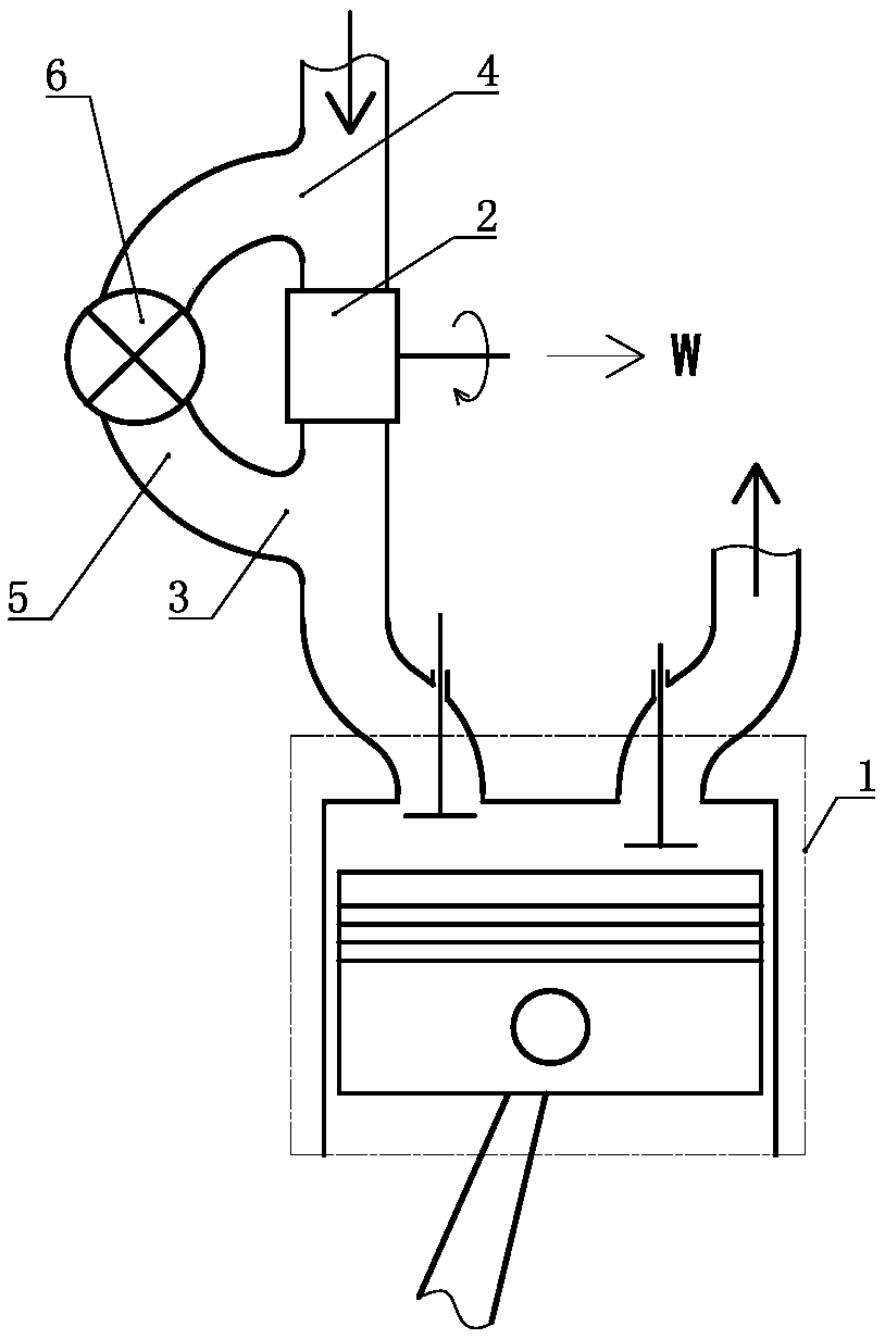
[0022] A mode switchable Miller cycle logic engine such as figure 1 As shown, a cylinder-piston mechanism 1 is included, and the cylinder-piston mechanism 1 is set as an adjustable compression ratio cylinder-piston mechanism. A seat opening bypass port 3 is provided on the communication channel between the working mechanism 2 and the air intake seat port, and an intake bypass port 4 is arranged on the working medium inlet passage of the working mechanism 2, and the seat port The port bypass port 3 communicates with the intake bypass port 4 via a bypass channel 5 , and a control valve 6 is arranged on the bypass channel 5 .

Embodiment 2

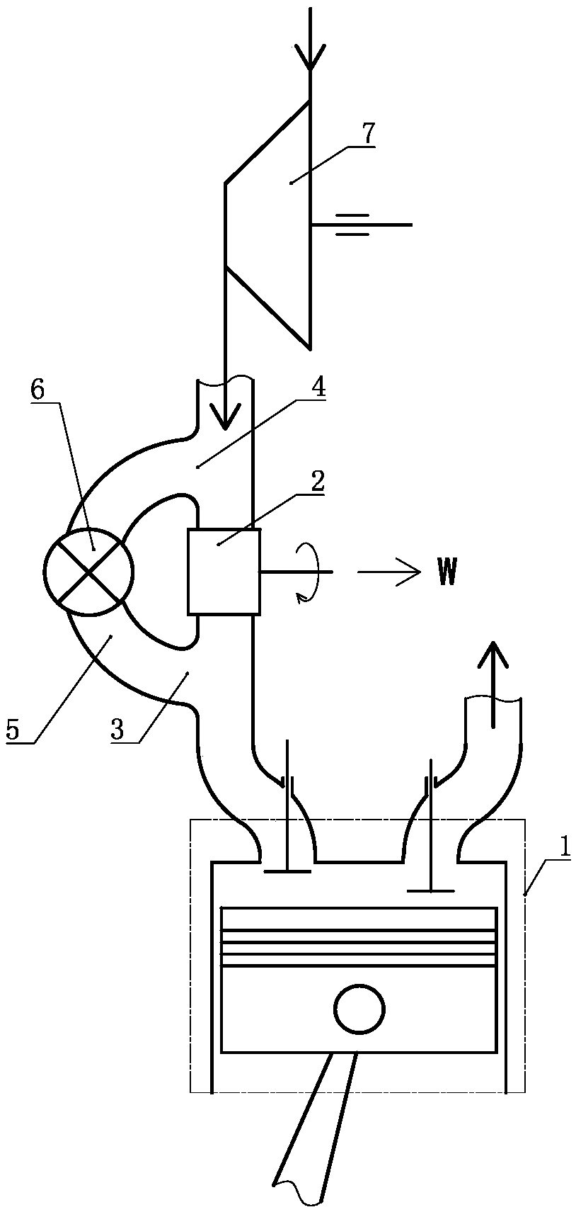
[0024] A mode switchable Miller cycle logic engine such as figure 2 As shown, a cylinder-piston mechanism 1 is included, and the cylinder-piston mechanism 1 is set as an adjustable compression ratio cylinder-piston mechanism. A seat opening bypass port 3 is provided on the communication channel between the working mechanism 2 and the air intake seat port, and an intake bypass port 4 is arranged on the working medium inlet passage of the working mechanism 2, and the seat port The bypass port 3 and the intake bypass port 4 are communicated with the bypass channel 5, and the control valve 6 is set on the bypass channel 5, and the working medium inlet of the working mechanism 2 and the working medium of the compressor 7 Quality export connectivity settings.

Embodiment 3

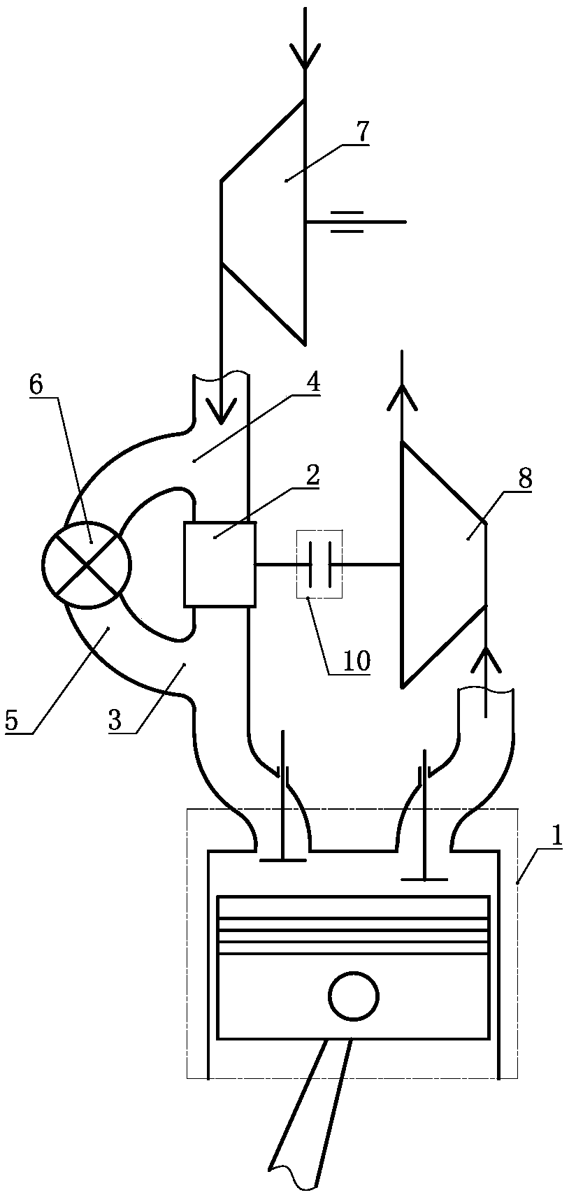
[0026] A mode switchable Miller cycle logic engine such as image 3 As shown, a cylinder-piston mechanism 1 is included, and the cylinder-piston mechanism 1 is set as an adjustable compression ratio cylinder-piston mechanism. A seat opening bypass port 3 is provided on the communication channel between the working mechanism 2 and the air intake seat port, and an intake bypass port 4 is arranged on the working medium inlet passage of the working mechanism 2, and the seat port The bypass port 3 and the intake bypass port 4 are communicated with the bypass channel 5, and the control valve 6 is set on the bypass channel 5, and the working medium inlet of the working mechanism 2 and the working medium of the compressor 7 The mass outlet is connected and set, the working mechanism 2 and the exhaust working mechanism 8 are set through the transmission of the clutch 10, the exhaust working mechanism 8 is arranged on the exhaust passage of the cylinder-piston mechanism 1, and the exhau...


PUM


Abstract

The invention discloses an engine with working condition capable of switching miller cycle logic. The engine comprises an air cylinder piston mechanism, wherein the air cylinder piston mechanism is set as the compression ratio-adjustable air cylinder piston mechanism, an air inlet seat port of the compression ratio-adjustable air cylinder piston mechanism communicates with a working medium outletof an acting mechanism, a communication channel between the acting mechanism and the air inlet seat port is provided with a seat port bypass port, a working medium inlet channel of the acting mechanism is provided with an air inlet bypass port, the seat port bypass port communicates with the air inlet bypass port through a bypass channel, and a control valve is arranged on the bypass channel. According to the engine with the working condition capable of switching the miller cycle logic, the load response is good, the efficiency is high, the power of the engine can be improved when the load isheavy, and meanwhile, the efficiency of the engine can be improved when the load is small.

Description

technical field [0001] The invention relates to the field of thermal energy and power, in particular to a miller cycle logic engine with switchable operating conditions. Background technique [0002] The Miller cycle is of great significance for improving the efficiency of the engine, but it will affect the power of the engine. The logic of the Miller cycle is to reduce the amount of intake air while expanding the volume of work. The logic of this cycle is called the logic of the Miller cycle. , since the real Miller cycle is realized by adjusting the closing time of the intake valve, it is difficult to switch and control in this way. If the same engine can be invented to have an engine that can work according to Miller cycle logic and non-Miller cycle logic, the load response capability and efficiency of the engine will be greatly improved. Therefore, a new type of engine needs to be invented. Contents of the invention [0003] In order to solve the above problems, the ...

Claims


Application Information

Patent Timeline
Patent Type & Authority Applications(China)
IPC IPC(8): F02B33/40F02B33/44F02D15/04F02B75/04F01D15/10
CPCF02B33/40F02B33/446F02D15/04F02B75/04F02B75/041F01D15/10F02B2275/32Y02T10/12
Inventor 靳北彪
Owner ENTROPY ZERO TECH LOGIC ENG GRP CO LTD
Learn More