
Drilling fluid cup assembly for drilling engineering filtration instrument

A technology for drilling fluid cups and drilling engineering, which is applied in the fields of filtration and separation, chemical instruments and methods, and fixed filter element filters. Filtration area, improved accuracy, and improved filtration efficiency

Active Publication Date: 2019-11-22
莒县翔威钻探有限公司
View PDF5 Cites 0 Cited by
  • Summary
  • Abstract
  • Description
  • Claims
  • Application Information

AI Technical Summary

Problems solved by technology

[0003] However, since the filter screen 8 is horizontally arranged at the bottom of the inner cavity of the drilling fluid cup 1, during the filtration process of the drilling fluid, it passes through the filter screen 8 and is collected by the filtrate hole 201. At this time, a filter cake is formed above the filter screen 8. With the increase of filter loss time, the increase of filter cake will affect the filtration efficiency of subsequent drilling fluid, thereby reducing the filtration efficiency of drilling fluid, and because the filter screen 8 and the stirring shaft 6 have a certain distance, the remaining When it is less, the filter cake is easy to block the filter screen 8, resulting in a small amount of drilling fluid that cannot pass through the filter screen 8, thus affecting the accuracy of the drilling fluid fluid loss

Method used


Image

  • Drilling fluid cup assembly for drilling engineering filtration instrument
  • Drilling fluid cup assembly for drilling engineering filtration instrument
  • Drilling fluid cup assembly for drilling engineering filtration instrument

Examples


Embodiment Construction

[0017] The following will clearly and completely describe the technical solutions in the embodiments of the present invention with reference to the accompanying drawings in the embodiments of the present invention. Obviously, the described embodiments are only some, not all, embodiments of the present invention. Based on the embodiments of the present invention, all other embodiments obtained by persons of ordinary skill in the art without making creative efforts belong to the protection scope of the present invention.

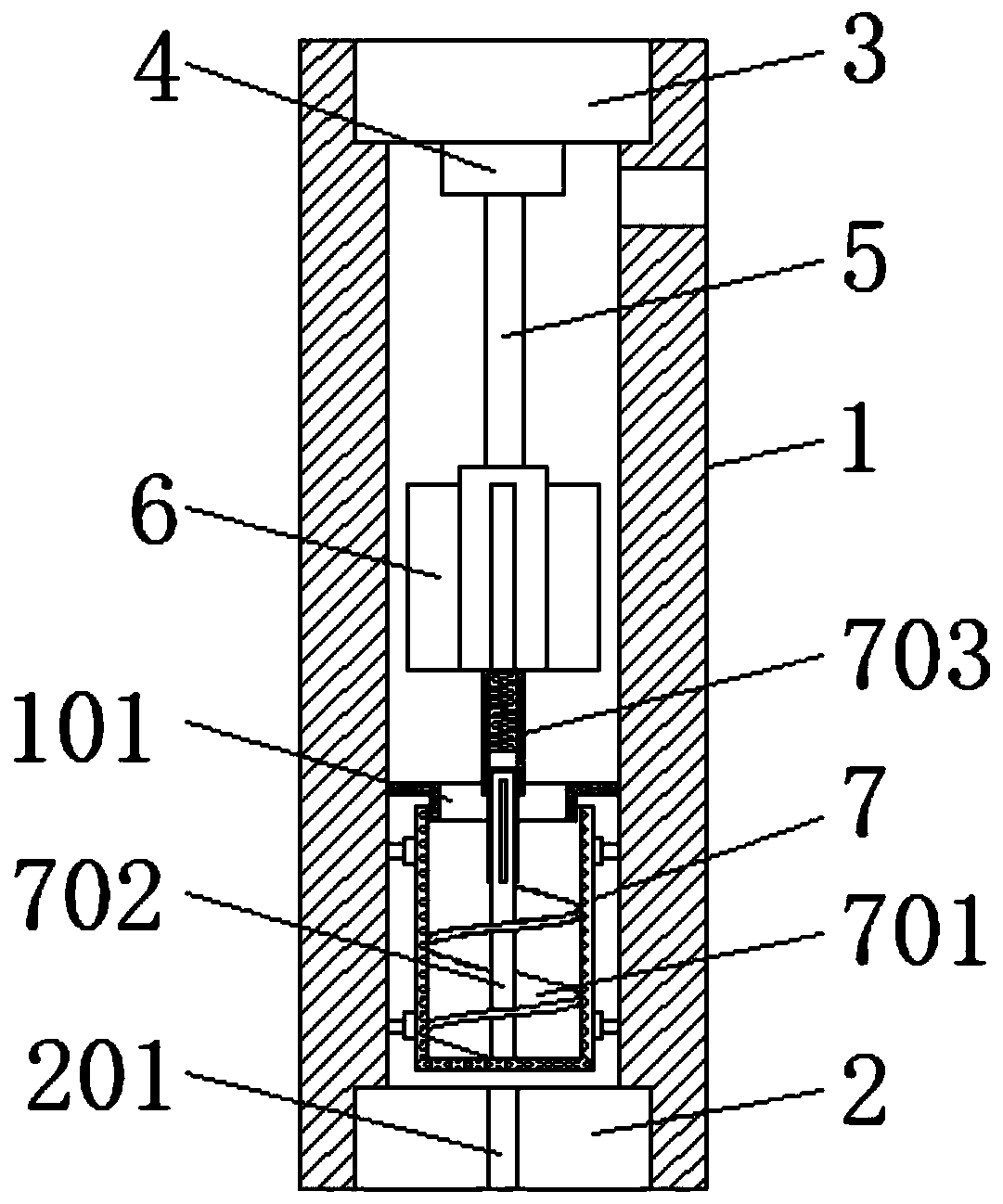
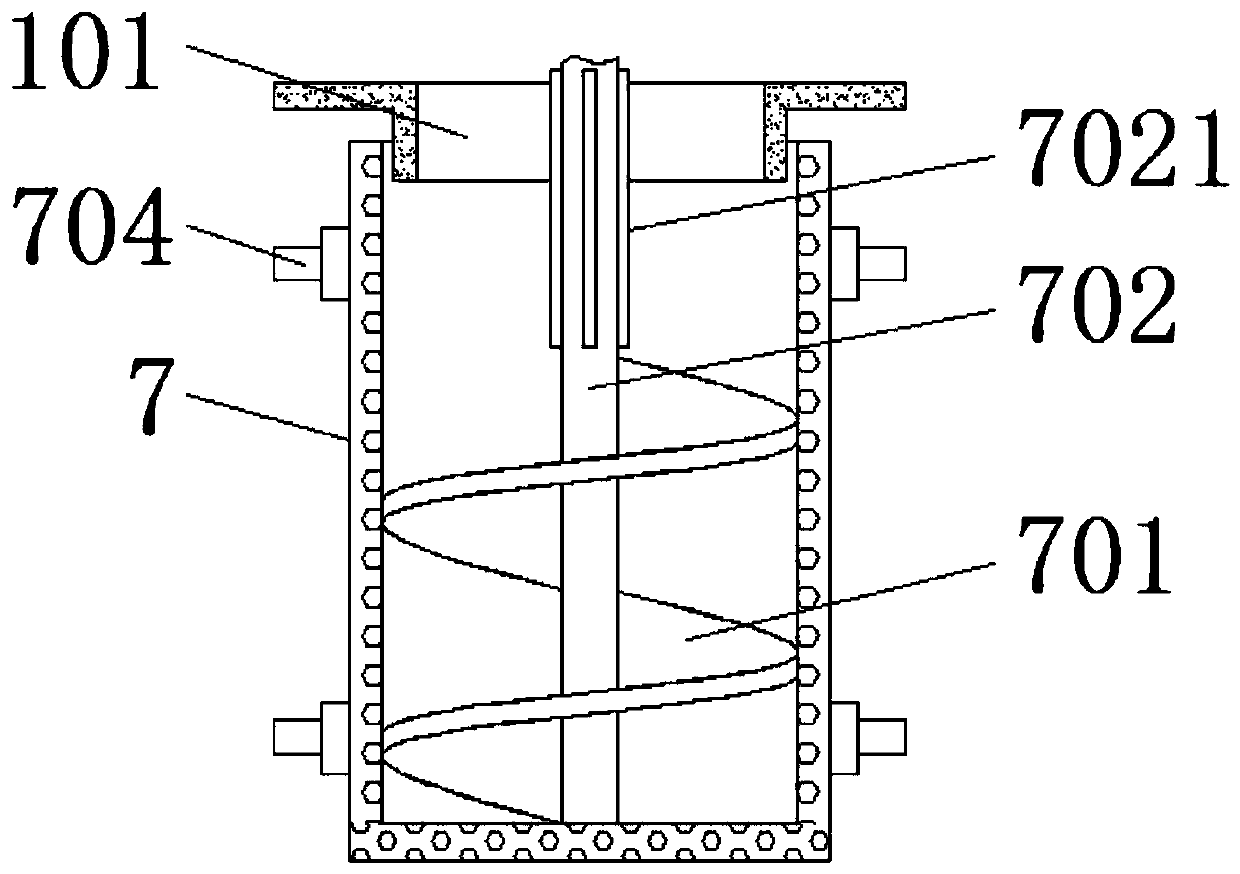
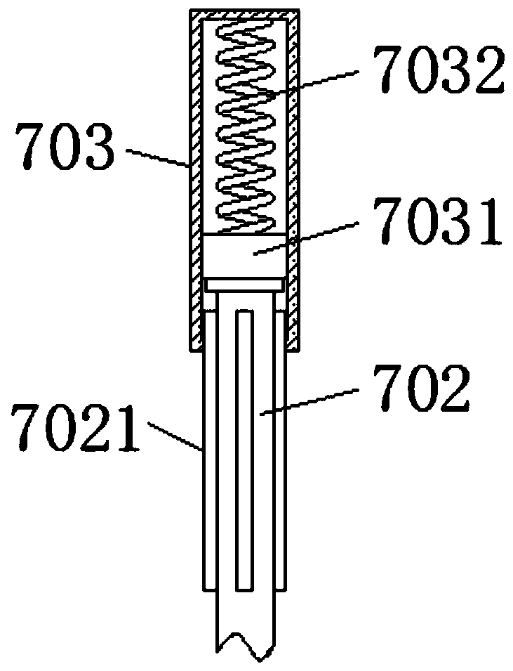
[0018] see Figure 1-3 , a drilling fluid cup assembly for a fluid loss meter in drilling engineering, comprising a drilling fluid cup 1, a lower cup cover 2, a filtrate hole 201, an upper cup cover 3, a rotating shaft main body 4, a rotating shaft 5, a stirring shaft 6, and a filter screen member 7 , the lower cup cover 2 is threaded on the bottom of the drilling fluid cup 1, and a sealing ring is provided to ensure that the drilling fluid in the inner cavity...


PUM


Abstract

The invention relates to the field of drilling instruments and meters. The utility model further discloses a drilling fluid cup assembly for the drilling engineering filtration instrument. The drilling fluid cup assembly comprises a drilling fluid cup, a lower cup cover, a filtrate hole, an upper cup cover, a rotating shaft main body, a rotating shaft and a stirring shaft, the rotating shaft mainbody, the rotating shaft and the stirring shaft form an internal stirring mechanism, a filter screen piece located below the stirring shaft is fixed to the bottom of an inner cavity of the drilling fluid cup, and the filter screen piece is designed to be cylindrical. According to the invention, the filter screen arranged at the bottom of the drilling fluid cup is replaced by the cylindrical filterscreen piece; the drilling fluid is filtered on two sides and at the bottom of the filter screen piece; and through rotation of the spiral blades, filter residues located at the bottom of the filterscreen piece move upwards, it is ensured that the filter residues do not influence subsequent drilling fluid filtration, the accuracy of the drilling fluid filtration amount is improved, the inner wall of the filter screen piece is swept when the spiral blades rotate, the spiral blades are not blocked by the filter residues, and the drilling fluid filtration efficiency is improved.

Description

technical field [0001] The invention relates to the field of drilling instruments, in particular to a drilling fluid cup assembly for a fluid loss meter in drilling engineering. Background technique [0002] The filter loss meter is a kind of simulating the filtration loss of drilling fluid and cement slurry under high temperature and high pressure in deep wells. At the same time, it can prepare the filter cake formed after the filter loss under high temperature and high pressure. The drilling fluid cup assembly is a must for the filter loss meter. One of the indispensable parts, the working principle of the drilling fluid cup is as follows Figure 4 : inject the drilling fluid into the drilling fluid cup 1, pressurize the top of the inner cavity of the drilling fluid cup 1, cooperate with the rotating shaft 5 to drive the stirring shaft 6 to rotate and stir evenly, so that the drilling fluid penetrates the filter screen 8 and the filtrate hole 201 , the fluid loss is obtain...

Claims


Application Information

Patent Timeline
Patent Type & Authority Applications(China)
IPC IPC(8): B01D29/35B01D29/64B01D29/86B01D29/92B01D29/94
CPCB01D29/35B01D29/6476B01D29/86B01D29/92B01D29/94
Inventor 戚春凤
Owner 莒县翔威钻探有限公司
Learn More