5G signal enhancement adjusting device
A technology of signal enhancement and adjustment device, applied in the direction of supporting machine, mechanical equipment, machine/stand, etc., can solve the problems of inability to signal enhancement, inconvenient adjustment of the direction of the signal enhancement device, etc., to achieve increased working area, convenient assembly and disassembly, Avoid displacement or shedding effects
- Summary
- Abstract
- Description
- Claims
- Application Information
AI Technical Summary
Problems solved by technology
Method used
Image

Examples
specific Embodiment approach 1
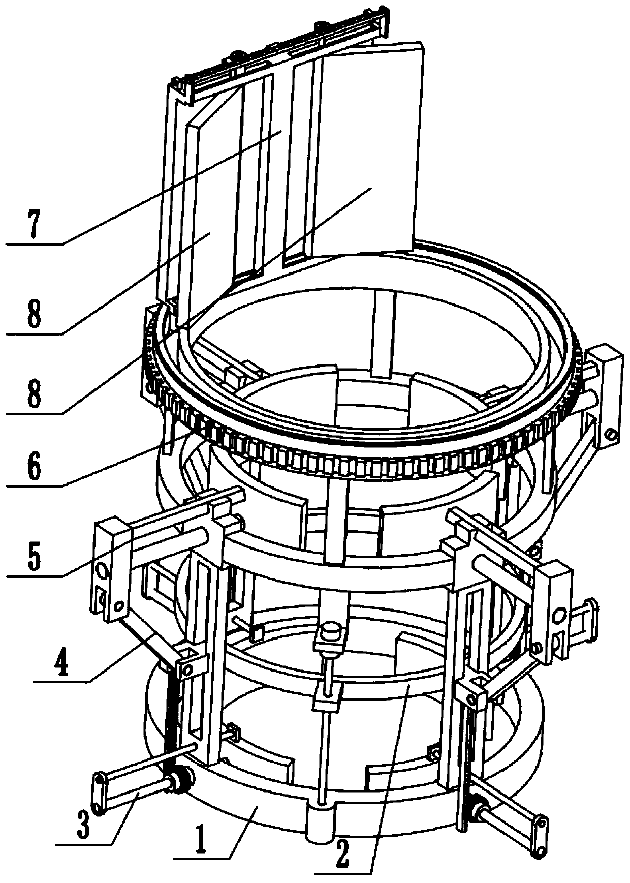
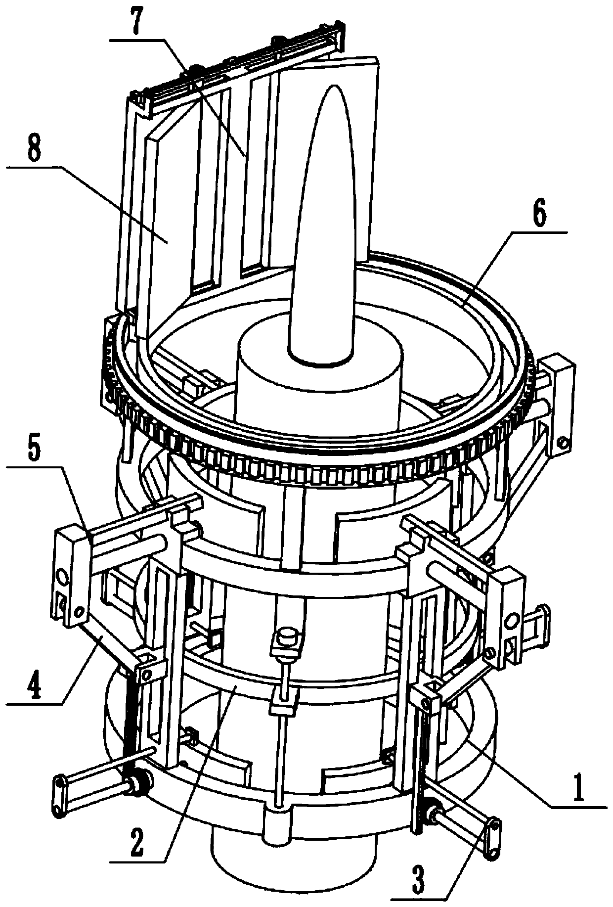
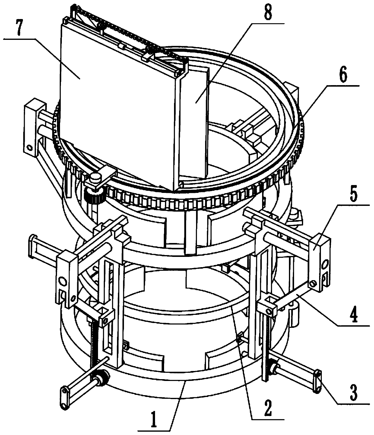
[0030] Combine below Figure 1-12Describe this embodiment, a 5G signal signal enhancement adjustment device, including a fixed frame 1, a loading and unloading control mechanism 2, a lower fixing member 3, a hinged rod 4, an upper fixing member 5, an angle adjustment seat 6, a direction adjustment enhancement component 7 and Angle adjustment reinforcement assembly 8, the loading and unloading control mechanism 2 is arranged in the middle of the fixed frame 1, four lower fixing parts 3 are arranged, and the four lower fixing parts 3 are evenly arranged around the lower end of the fixed frame 1, and the loading and unloading control The mechanism 2 is connected to the four lower fixing parts 3 by transmission, the loading and unloading control mechanism 2 is evenly hinged around four hinged rods 4, and there are four upper fixing parts 5, and the four upper fixing parts 5 are evenly arranged on the fixed frame 1. At the upper end, the upper ends of the four articulated rods 4 ar...
specific Embodiment approach 2
[0032] Combine below Figure 1-12 To illustrate this embodiment, the fixed frame 1 includes a circular bottom frame 1-1, a vertical frame plate 1-2, a rectangular through slot 1-3, an upper fixing seat 1-4, an arc-shaped connecting rod 1-5, Motor I 1-6 and lead screw 1-7; the upper end of the circular bottom frame 1-1 is evenly surrounded and fixedly connected to four vertical frame plates 1-2, and the four vertical frame plates 1-2 are all provided with rectangular through slots 1- 3. The upper ends of the four vertical frame plates 1-2 are respectively fixedly connected to an upper fixing seat 1-4, and the four upper fixing seats 1-4 and the four arc-shaped connecting rods 1-5 are interlaced and fixedly connected at intervals, and the motor Ⅰ1-6 The motor frame is fixedly connected to an arc-shaped connecting rod 1-5, the output shaft of the motor Ⅰ1-6 is connected to the screw 1-7 through a coupling, and the lower end of the screw 1-7 is connected to the circular shaft thro...
specific Embodiment approach 3
[0034] Combine below Figure 1-12 To illustrate this embodiment, the loading and unloading control mechanism 2 includes a ring frame 2-1, a hinged seat 2-2, a rack I 2-3 and a linkage block 2-4; the outer end of the ring frame 2-1 is uniformly surrounded and fixedly connected A hinged seat 2-2, the lower ends of the four hinged seats 2-2 are respectively fixedly connected to a rack I 2-3, and the linkage block 2-4 is fixedly connected to the ring frame 2-1; the ring frame 2-1 is located on four The inner side of a vertical frame plate 1-2, four hinged seats 2-2 are respectively slidingly fitted and connected in four rectangular through grooves 1-3, and the lower ends of four hinged rods 4 are respectively connected to the four hinged seats by hinged shaft rotation. On 2-2, the linkage block 2-4 is connected to the lead screw 1-7 through thread fit; When the loading and unloading control mechanism 2 is in use, the motor I1-6 is connected to the power supply and the control swi...
PUM
 Abstract
Description
Claims
Application Information
 - R&D
- Intellectual Property
- Life Sciences
- Materials
- Tech Scout
- Unparalleled Data Quality
- Higher Quality Content
- 60% Fewer Hallucinations
Browse by: Latest US Patents, China's latest patents, Technical Efficacy Thesaurus, Application Domain, Technology Topic, Popular Technical Reports.
© 2025 PatSnap. All rights reserved.Legal|Privacy policy|Modern Slavery Act Transparency Statement|Sitemap|About US| Contact US: help@patsnap.com