
Permanent magnet synchronous variable frequency motor rotor punching tool

A variable frequency motor and rotor punching technology, which is applied in the mechanical field, can solve the problems of damage to the positioning keyway, difficulty in the punching process, unequal punching grooves, etc., and achieve good uniformity, save production costs and time, and smooth installation.

Pending Publication Date: 2019-11-19
FUSHUN COAL MINE MOTOR MFG
View PDF0 Cites 0 Cited by
  • Summary
  • Abstract
  • Description
  • Claims
  • Application Information

AI Technical Summary

Problems solved by technology

Compared with the traditional electronic rotor punching, the rotor punching of the permanent magnet synchronous frequency conversion motor has more complicated slots and inaccurate positioning. During the punching process, quality problems such as damage to the positioning keyway and unequal punching are prone to occur. very difficult process

Method used


Image

  • Permanent magnet synchronous variable frequency motor rotor punching tool
  • Permanent magnet synchronous variable frequency motor rotor punching tool
  • Permanent magnet synchronous variable frequency motor rotor punching tool

Examples


Embodiment Construction

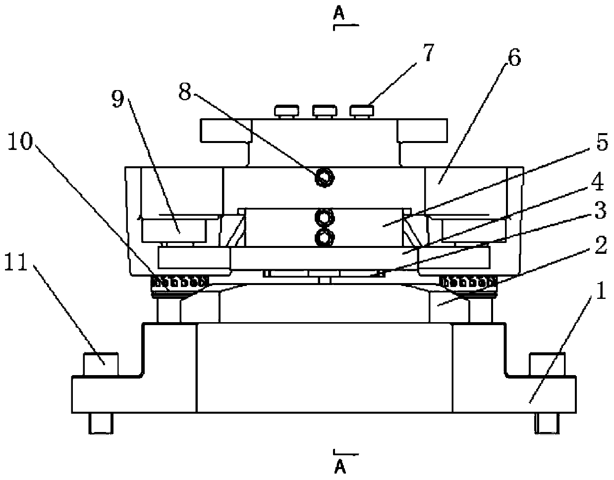
[0033] The present invention is specifically described below in conjunction with accompanying drawing, as shown in the figure, the present invention comprises mold, center positioning device;

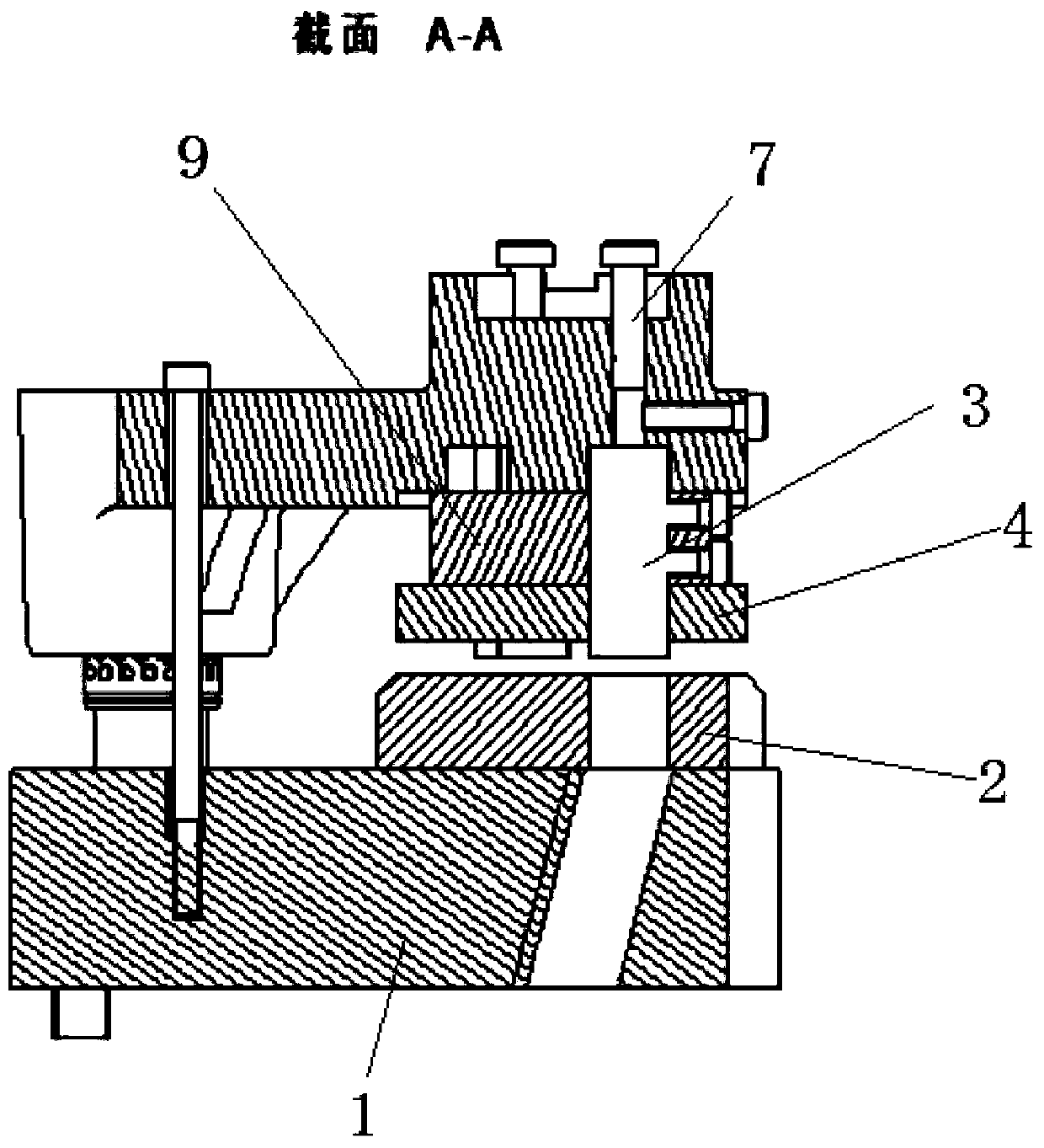
[0034] The mold includes a lower mold base 1, a lower mold 2, a punch 3, a stripping plate 4, a fixing plate 5, and an upper mold base 6; a buffer reset device 9; a guide post guide sleeve 10; a bolt 11;

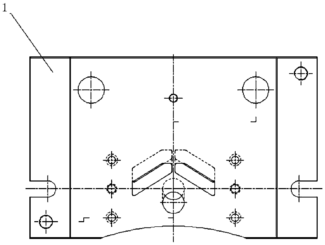
[0035] The lower mold base 1 is provided with a blanking slot, the bottom end is connected with the punching machine workbench through a screw 11, and the top is connected with the lower mold 2; The lower mold base 1 is connected; the grooved punch 3 is fixed on the fixed plate 5 through the set screw; the fixed plate 5 is fixed on the bottom of the upper mold frame 6; Pass through the grooved punch 3 and abut against the lower end of the buffer reset mechanism 9;

[0036] The lower mold base is provided with a slope-shaped notch, so that the punching waste can smoothly fall into the...


PUM


Abstract

The invention discloses a permanent magnet synchronous variable frequency motor rotor punching tool. The top end of an upper mold frame is connected with a punching machine, and the bottom end of theupper mold frame is connected with a lower mold base through a guide column and guide sleeve; a groove-shaped punch is fixed on a fixing plate through a fastening screw, a buffer reset mechanism is arranged at the lower end of the upper mold frame, and a material returning plate penetrates through the groove-shaped punch and is abutted against the lower end of the buffer reset mechanism; the bottom end of the lower mold base is connected with a punching machine worktable through screws, and the top end of the lower mold base is connected with a lower mold; and the topend of the upper mold frame is connected with the punching machine, the bottom end of the upper mold frame is connected with the lower mold base through the guide column and guide sleeve, the groove-shaped punch is fixed to the fixing plate through the fastening screw, the fixing plate is fixed at the bottom end of the upper mold frame, and the material returning plate penetrates through the groove-shaped punch and is abutted against the lower end of the buffer reset mechanism. The tool has the advantages that 1, the precision is high, the minimum distance between notches is guaranteed to be 2 mm, and the drawing requirements of rotor punching are met; 2, after installation and pressing, the uniformity is good, and the installation of a permanent magnet is guaranteed; and 3, the structure is simple, and machining is simple and convenient.

Description

technical field [0001] The invention relates to the field of machinery, in particular to a permanent magnet synchronous variable frequency motor rotor punching tool. Background technique [0002] In the production process of permanent magnet motors, the stamping process of stator and rotor punching plays an important role. The punching method used in the prior art is to use a high-speed notching machine, the mold is positioned at the center, and the high-precision guide frame is used to drive the punch to rotate, and the press drives the mold to move up and down. [0003] Stamping to produce groove shape. Compared with the traditional electronic rotor punching, the rotor punching of the permanent magnet synchronous frequency conversion motor has more complicated slots and inaccurate positioning. During the punching process, quality problems such as damage to the positioning keyway and unequal punching are prone to occur. The process is very difficult. Contents of the inv...

Claims


Application Information

Patent Timeline
Patent Type & Authority Applications(China)
IPC IPC(8): B21D28/14H02K15/02
CPCB21D28/14H02K15/02Y02P70/10
Inventor 张思思李洪生曹建春夏青李微
Owner FUSHUN COAL MINE MOTOR MFG
Learn More