Textile machinery supporting device

A technology for supporting devices and textile machinery, which is applied to mechanical equipment, machines/brackets, supporting machines, etc., can solve the problems of reducing the service life of the supporting device, inability to adjust the supporting height, damage to the supporting device, etc., to achieve easy installation and fixation, practical Strong performance and long service life

Inactive Publication Date: 2019-11-15
枣阳市博大纺织有限公司
View PDF0 Cites 3 Cited by
  • Summary
  • Abstract
  • Description
  • Claims
  • Application Information

AI Technical Summary

Problems solved by technology

In textile machinery, it is necessary to use support devices to support it. The existing support devices cannot adjust the support height according to the needs, and cannot meet the requirements of different machines for different heights from the ground. Moreover, due to the vibration associated with the operation of the machine, it will affect the support. The device causes serious damage and reduces the service life of the support device. For this reason, we propose a textile machinery support device

Method used


Image

  • Textile machinery supporting device
  • Textile machinery supporting device
  • Textile machinery supporting device

Examples


Embodiment 1

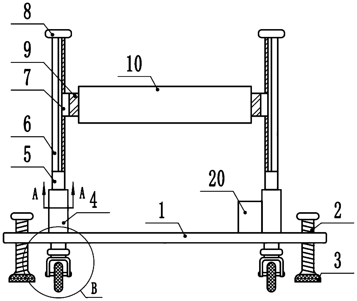
[0024] see Figure 1-4 , a textile machinery supporting device, comprising a base 1, the upper surface of the base 1 is fixedly connected to the left and right sides of the fixed seat 4, the interior of the upper part of the fixed seat 4 is hollow, and the interior of the fixed seat 4 is provided with a chute 13, the bottom of the chute 13 A spring 14 is fixedly connected, the upper end of the spring 14 is elastically fixedly connected with a fixed rod 5, the side of the fixed rod 5 is contacted with the side wall of the chute 13, and the upper end of the fixed rod 5 is fixedly connected with a slide rail 6, and the number of the slide rails 6 is two One, the inner surface of the two slide bars is slidably equipped with a slide cylinder 7, and the slide rail 6 is fixedly connected with a limit block 8 at one end of the fixed rod 5, so as to prevent the slide cylinder 7 from sliding out of the slide rail 6 and play a position-limiting role.

[0025] Specifically, a fixed block ...

Embodiment 2

[0028] see Figure 1-4 , a textile machinery supporting device, comprising a base 1, the upper surface of the base 1 is fixedly connected to the left and right sides of the fixed seat 4, the interior of the upper part of the fixed seat 4 is hollow, and the interior of the fixed seat 4 is provided with a chute 13, the bottom of the chute 13 A spring 14 is fixedly connected, the upper end of the spring 14 is elastically fixedly connected with a fixed rod 5, the side of the fixed rod 5 is contacted with the side wall of the chute 13, and the upper end of the fixed rod 5 is fixedly connected with a slide rail 6, and the number of the slide rails 6 is two One, the inner surface of the two slide bars is slidably equipped with a slide cylinder 7, and the slide rail 6 is fixedly connected with a limit block 8 at one end of the fixed rod 5, so as to prevent the slide cylinder 7 from sliding out of the slide rail 6 and play a position-limiting role.

[0029] Specifically, a fixed block ...


PUM


Abstract

The invention discloses a textile machinery supporting device. The textile machinery supporting device comprises a foundation base, fixing bases are fixedly connected to the left side and the right side of the upper surface of the foundation base, the interiors of the upper parts of the fixing bases are of hollow structures, sliding grooves are formed in the fixing bases, springs are fixedly connected to the bottoms of the sliding grooves, fixing rods are elastically and fixedly connected to the upper ends of the springs, the side surfaces of the fixing rods are connected to the side walls ofthe sliding grooves in a contact mode, two sliding rails are fixedly connected to the upper ends of the fixing rods, sliding cylinders are arranged on the inner surfaces of the two sliding rods in a sliding mode, fixing blocks are fixedly connected to the sides, far away from the sliding rails, of the sliding cylinders, and a supporting base is fixedly connected between the fixing blocks. According to the textile machinery supporting device, the supporting base can ascend and descend, the installation and fixation of textile machinery are facilitated, furthermore, the requirements of differentmachinery on different terrain clearances are met, in addition, in the working process of the textile machinery, through the fixing rods and the springs, vertical buffering in the fixing bases can berealized, so that a very good damping effect is achieved, equipment is safer and more durable, the service life is long, and the practicability is high.

Description

technical field [0001] The invention specifically relates to the field of textile machinery, in particular to a textile machinery support device. Background technique [0002] The original meaning of textile is taken from the general term of spinning and weaving, but with the continuous development and improvement of the textile knowledge system and subject system, especially after the emergence of non-woven textile materials and three-dimensional composite weaving technologies, textile is not only the traditional spinning and weaving Weaving also includes non-woven technology, three-dimensional weaving technology, electrostatic nano-netting technology, etc. Weaving is roughly divided into two processes: spinning and weaving. According to legend, the origin of Chinese textiles began with Leizu raising silkworms and smelting silk. Archaeologists found bone needles on the archaeological site of the Upper Cave Man in the Paleolithic Age, which is the earliest known origin of t...

Claims


Application Information

Patent Timeline
Patent Type & Authority Applications(China)
IPC IPC(8): F16M11/04F16M11/18F16M11/24F16F15/04
CPCF16F15/04F16F2238/026F16M11/046F16M11/18F16M11/24
Inventor 张荣清
Owner 枣阳市博大纺织有限公司
Why Eureka
Try Eureka