Intelligent water pouring table
A smart, table-leg technology, applied in the field of pouring tables, can solve problems such as weakness, the possibility of pouring water out of the cup, and difficulty in pouring water for patients
- Summary
- Abstract
- Description
- Claims
- Application Information
AI Technical Summary
Problems solved by technology
Method used
Image

Examples
Embodiment 1
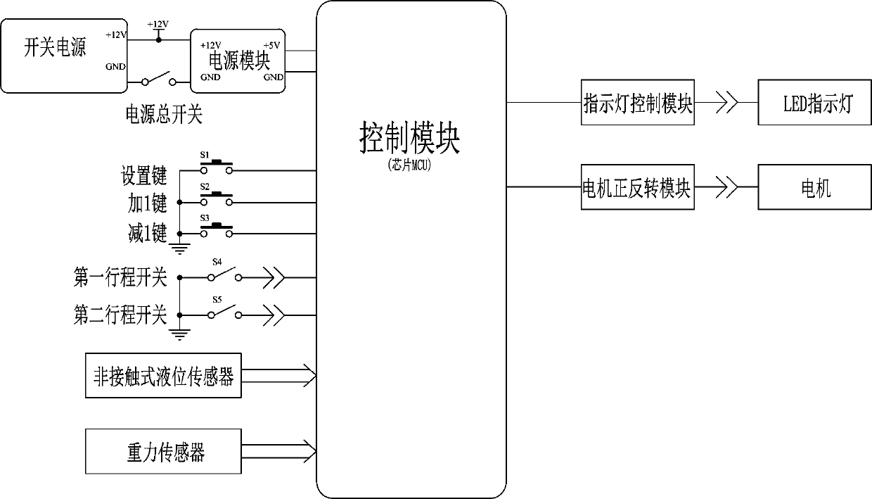
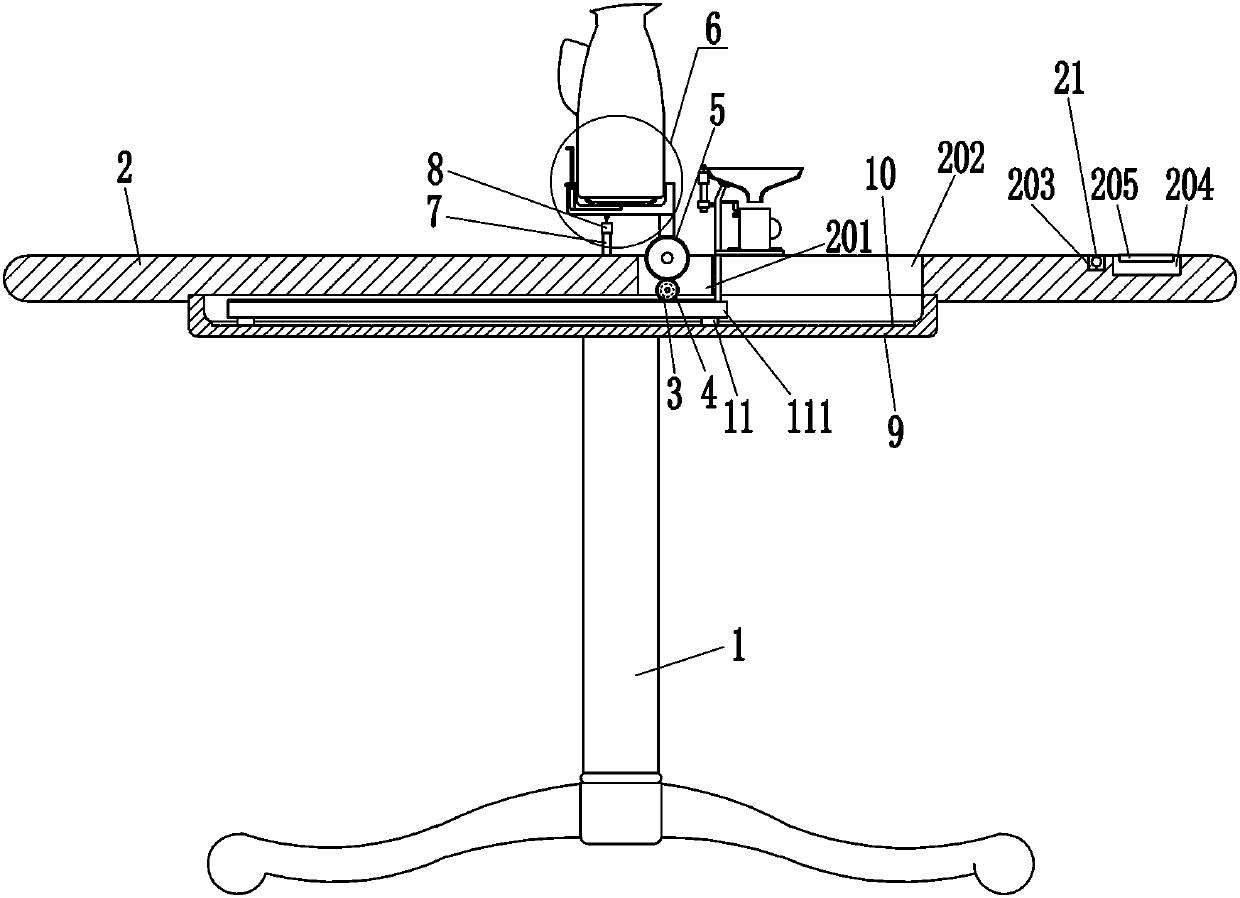
[0018] A smart pouring table, such as Figure 1-4 As shown, it includes table legs 1, desktop 2, control box 204, control panel 205, motor 3, small gear 4, large gear 5, clamping mechanism 6, first pole 7, first travel switch 8, U-shaped Frame 9, slider 11, rack 111, second pole 12 and flat tray 13, desktop 2 is installed on the top of table leg 1, the middle part of desktop 2 has a first groove 201, and the right part of desktop 2 has a word groove 202, There is a second groove 203 on the right side of the top of the desktop 2, and a control box 204 is embedded in the right side of the top of the desktop 2. The control box 204 is located on the right side of the second groove 203. The control box 204 includes a switching power supply, a power module and The control module, the output end of the switching power supply and the power supply module are connected by lines, the power supply module and the control module are connected by lines, the power supply module is connected w...
Embodiment 2
[0020] A smart pouring table, such as Figure 1-4 As shown, it includes table legs 1, desktop 2, control box 204, control panel 205, motor 3, small gear 4, large gear 5, clamping mechanism 6, first pole 7, first travel switch 8, U-shaped Frame 9, slider 11, rack 111, second pole 12 and flat tray 13, desktop 2 is installed on the top of table leg 1, the middle part of desktop 2 has a first groove 201, and the right part of desktop 2 has a word groove 202, There is a second groove 203 on the right side of the top of the desktop 2, and a control box 204 is embedded in the right side of the top of the desktop 2. The control box 204 is located on the right side of the second groove 203. The control box 204 includes a switching power supply, a power module and The control module, the output end of the switching power supply and the power supply module are connected by lines, the power supply module and the control module are connected by lines, the power supply module is connected w...
Embodiment 3
[0023] A smart pouring table, such as Figure 1-4 As shown, it includes table legs 1, desktop 2, control box 204, control panel 205, motor 3, small gear 4, large gear 5, clamping mechanism 6, first pole 7, first travel switch 8, U-shaped Frame 9, slider 11, rack 111, second pole 12 and flat tray 13, desktop 2 is installed on the top of table leg 1, the middle part of desktop 2 has a first groove 201, and the right part of desktop 2 has a word groove 202, There is a second groove 203 on the right side of the top of the desktop 2, and a control box 204 is embedded in the right side of the top of the desktop 2. The control box 204 is located on the right side of the second groove 203. The control box 204 includes a switching power supply, a power module and The control module, the output end of the switching power supply and the power supply module are connected by lines, the power supply module and the control module are connected by lines, the power supply module is connected w...
PUM
 Abstract
Description
Claims
Application Information
 - R&D
- Intellectual Property
- Life Sciences
- Materials
- Tech Scout
- Unparalleled Data Quality
- Higher Quality Content
- 60% Fewer Hallucinations
Browse by: Latest US Patents, China's latest patents, Technical Efficacy Thesaurus, Application Domain, Technology Topic, Popular Technical Reports.
© 2025 PatSnap. All rights reserved.Legal|Privacy policy|Modern Slavery Act Transparency Statement|Sitemap|About US| Contact US: help@patsnap.com