
Composite position error compensation method and device

An error compensation and error technology, which is applied in the application field of ultra-precision motion control, can solve the problems of multi-dimensional non-uniform distribution error, discrete non-uniform distribution, and complex error surface reconstruction work, and achieves high composite position error compensation and high complexity. degree of effect

Active Publication Date: 2019-11-08
苏州行远志成自动化科技有限公司
View PDF11 Cites 2 Cited by
  • Summary
  • Abstract
  • Description
  • Claims
  • Application Information

AI Technical Summary

Problems solved by technology

Due to the fact that various nonlinear deformations or random noises often exist in the actual electromechanical system, the position distribution of the actual measurement points presents a discrete and non-uniform distribution, which makes the reconstruction of the error surface extremely complicated.
Taking the high-precision wafer probe station as an example, due to the nonlinear deformation of the wafer caused by the vacuum adsorption device and other compound errors and random noise in the system, there are multi-dimensional non-uniform distribution errors in the measured compound error points, which makes subsequent Reconstruction of composite position error surfaces becomes extremely complex
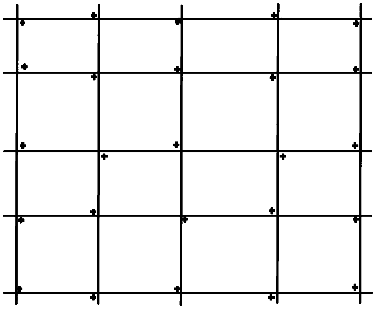
[0004] like figure 1 As shown, due to the non-linear deformation of the wafer caused by the vacuum suction device and the combination of non-linear errors and random noise of other mechanisms, the measurement points that should be collinear appear in 2D non-linearity after the pixel alignment correction of the high-resolution camera. The situation of uniform distribution makes the reconstruction of the spatial composite position error surface extremely complicated in the later stage

Method used


Image

  • Composite position error compensation method and device
  • Composite position error compensation method and device
  • Composite position error compensation method and device

Examples


Embodiment 1

[0060] An embodiment of the present invention provides a compound position error compensation method, including the following steps:

[0061] (1) Correcting the acquired original multi-dimensional non-uniformly distributed discrete measured position data into several groups of one-dimensional non-uniformly distributed corrected position data, the corrected position data storing the error data generated by the correction;

[0062] (2) Curve reconstruction is performed on each group of one-dimensional non-uniformly distributed corrected position data to form corresponding one-dimensional uniformly distributed corrected position data;

[0063] (3) Carry out curve reconstruction based on all one-dimensional uniformly distributed corrected position data, obtain subdivided position data of uniform grid points, and then obtain a reconstructed surface;

[0064] (4) Generate a corresponding compensation table based on the reconstructed curved surface for realizing compound position err...

Embodiment 2

[0106] The difference between the embodiment of the present invention and embodiment 1 is that the method further includes:

[0107] Based on the compensation table, the online compensation of the measured position data is performed.

Embodiment 3

[0109] Based on the same inventive concept as in Embodiment 1, a compound position error compensation device is provided in the embodiment of the present invention, including:

[0110] A correction module, configured to correct the obtained original multi-dimensional non-uniformly distributed discrete measured position data into several sets of one-dimensional non-uniformly distributed corrected position data, wherein the corrected position data stores the error data generated by the correction;

[0111] The first reconstruction module is used to perform curve reconstruction on each group of one-dimensional non-uniformly distributed corrected position data to form corresponding one-dimensional uniformly distributed corrected position data;

[0112] The second reconstruction module is used to perform curve reconstruction based on all one-dimensional uniformly distributed corrected position data, obtain uniform grid point subdivision position data, and then obtain a reconstructed...


PUM


Abstract

The invention discloses a composite position error compensation method and device. The method comprises: correcting obtained original discrete actually-measured position data in a multi-dimensional non-uniform distributed manner into a plurality of sets of corrected position data storing error data that are generated by correction and are in a one-dimensional non-uniform distributed manner; carrying out curve reconstruction on the corrected position data in a one-dimensional non-uniform distributed manner in all sets to form corresponding corrected position data in a one-dimensional uniform distributed manner; carrying out curve reconstruction on all corrected position data in a one-dimensional uniform distributed manner, acquiring subdivision position data of uniform grid points, and thusacquiring a reconstructed curved surface; and generating a corresponding compensation table based on the reconstructed curved surface to realize composite position error compensation. According to the invention, the original discrete actually-measured position data in a multi-dimensional non-uniform distributed manner are corrected, error reconstruction is carried out based on the corrected data,and thus the compensation table is generated. Therefore, the high-precision and high-complexity composite position error compensation is realized.

Description

technical field [0001] The invention belongs to the technical field of ultra-precision motion control applications, relates to a compound position error compensation method, and more particularly relates to a compound position error compensation method and device based on non-uniform discrete compound position errors. Background technique [0002] At present, in high-precision and ultra-precision motion control systems, compound error compensation including various mechanical and electrical imperfections has become an important means to obtain higher precision. Generally, simple error compensation methods such as 1D and 2D are common in most motion control systems. However, limited by the data storage space and real-time calculation speed of the data compensation table, usually a motion axis can only have extremely limited In the case of multi-dimensional cross compensation, both the number of compensation tables and the compensation method are greatly limited in complex hig...

Claims


Application Information

Patent Timeline
IPC IPC(8): G05B19/404G06F17/18
CPCG05B19/404G05B2219/31434G06F17/18
Inventor 刘政薛俊霞隋亮秦奥伟李昆鹏杨新论
Owner 苏州行远志成自动化科技有限公司
Learn More