
Cold and head energy accumulator

An accumulator, cooling and heating technology, applied in the direction of mechanical equipment, etc., can solve the problems of limitation, lack of installation position of the buffer device, etc., and achieve the effect of prolonging the service life and reducing loss

Inactive Publication Date: 2019-11-08
盐城明天和创环保节能科技有限公司
View PDF0 Cites 0 Cited by
  • Summary
  • Abstract
  • Description
  • Claims
  • Application Information

AI Technical Summary

Problems solved by technology

[0003] The purpose of the present invention is to solve the problem of lack of buffer device and limited installation position in the prior art, and the proposed cold and heat accumulator

Method used

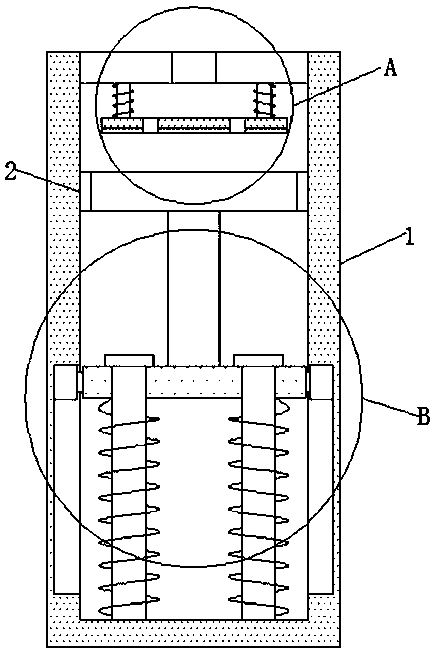

Image

  • Cold and head energy accumulator
  • Cold and head energy accumulator
  • Cold and head energy accumulator

Examples


Embodiment Construction

[0016] The following will clearly and completely describe the technical solutions in the embodiments of the present invention with reference to the drawings in the embodiments of the present invention.

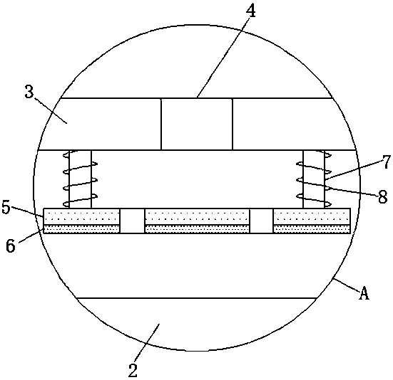
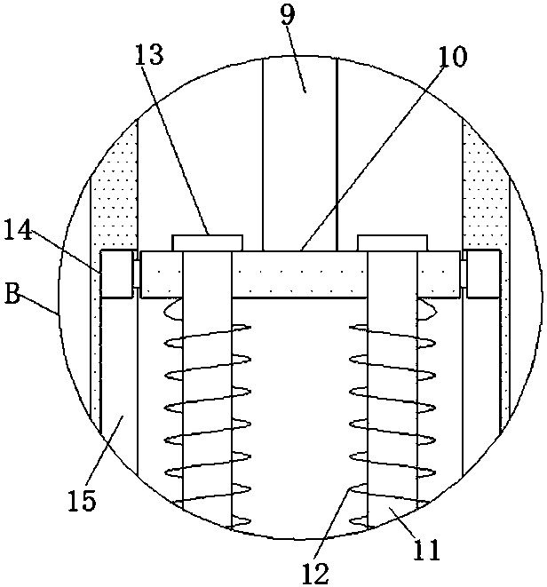
[0017] refer to Figure 1-3 , cold and hot accumulators, including an energy storage box 1, a piston 2 is installed on the inner wall of the energy storage box 1, a sealing cover 3 is fixedly installed on the energy storage box 1, and an air inlet 4 is opened on the sealing cover 3, and the sealing The cover 3 is equipped with a buffer device, which includes two telescopic rods 7 symmetrically fixedly installed on the outer wall of the sealing cover 3 near the piston 2, and the telescopic rods 7 are located on both sides of the air intake hole 4, and the two telescopic rods 7 A mounting plate 5 is fixedly installed at one end close to the piston 2, a cushion 6 is fixedly installed on the outer wall of the mounting plate 5 close to the piston 2, and a buffer spring 8 is set on ...


PUM


Abstract

The invention discloses a cold and head energy accumulator. The cold and head energy accumulator comprises an energy accumulating box; a piston is arranged on the inner side wall of the energy accumulating box; a sealing cover is fixedly arranged on the energy accumulating box; a gas inlet hole is formed in the sealing cover; a buffer device is arranged on the sealing cover; and a stable energy accumulating device is arranged in the energy accumulating box. The cold and head energy accumulator has the advantages that the buffer device is arranged on the sealing cover, the piston does not directly collided to the sealing cover, but collides to a cushion when rebounding, and a telescopic rod cooperates with a buffer spring to buffer an impact force, so loss of the sealing cover and the piston is reduced and the service life of equipment is prolonged; and the piston compresses an energy accumulating spring to accumulate energy and the energy accumulating spring is arranged on a guide rodin a sleeving way, so offset is avoided, energy is accumulated stably, cooperation of hydraulic oil and the piston is replaced and limitation of a mounting position is removed.

Description

technical field [0001] The invention relates to the technical field of accumulators, in particular to a cold and heat accumulator. Background technique [0002] The accumulator is an energy storage device in the hydraulic pneumatic system. It converts the energy in the system into compression energy or potential energy at an appropriate time and stores it. When the system needs it, it converts the compression energy or potential energy into hydraulic pressure. When the pressure of the system increases instantaneously, it can absorb this part of the energy to ensure the normal pressure of the entire system. The existing piston accumulator lacks a buffer device. For a piston accumulator without a buffer device, the piston will hit the end cover during high flow operation time, resulting in abnormal noise and a great impact on the life of the end cover and its piston. , Secondly, the existing piston accumulators all need to cooperate with hydraulic oil to store energy, but thi...

Claims


Application Information

Patent Timeline
Patent Type & Authority Applications(China)
IPC IPC(8): F15B1/04
CPCF15B1/04
Inventor 刘利平
Owner 盐城明天和创环保节能科技有限公司
Learn More