
Test device for simulating surface rupture deformation of reverse fault under earthquake

A test device, reverse fault technology, applied in the direction of measuring device, soil material test, material inspection product, etc., can solve the problem that large-scale and large-scale fault test cannot be completed well, the load power of loading device is small, and it is difficult to model Box staggered movement and other problems, to reduce casualties and property losses, strong operability, and strong repeatability

Pending Publication Date: 2019-11-05
INST OF DISASTER PREVENTION
View PDF0 Cites 2 Cited by
  • Summary
  • Abstract
  • Description
  • Claims
  • Application Information

AI Technical Summary

Problems solved by technology

[0003] At present, the common test devices for simulating fault dislocation mainly use small servo motors as loading devices, which have their own technical defects: (1) The loading power of the loading device at the bottom of the simulated box is relatively small, and cannot well complete large-scale, Large-scale fault tests; (2) It is technically difficult to achieve a balanced and uniform dislocation of the model box during the loading process, which will result in low accuracy of test results; (3) More test simulation boxes are uniform Due to its small size, it cannot well reproduce the real cracking of the overlying soil under fault dislocation

Method used


Image

  • Test device for simulating surface rupture deformation of reverse fault under earthquake
  • Test device for simulating surface rupture deformation of reverse fault under earthquake
  • Test device for simulating surface rupture deformation of reverse fault under earthquake

Examples


Embodiment Construction

[0023] In order to make the object, technical solution and advantages of the present invention clearer, the present invention will be further described in detail below with reference to the accompanying drawings and examples.

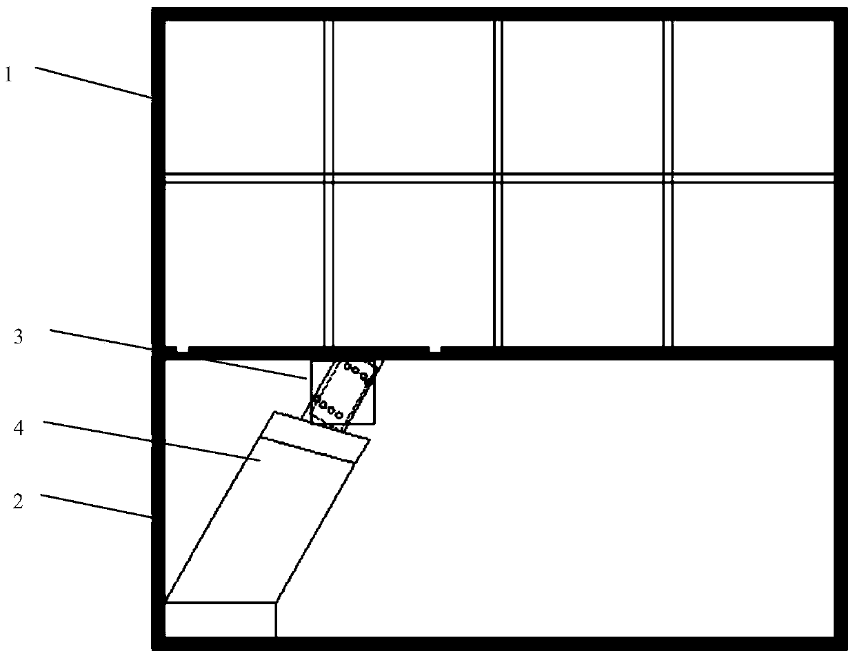
[0024] Such as figure 1 , 2 As shown, a test device for simulating surface rupture and deformation of a reverse fault under an earthquake, including: a reaction floor, a soil box 1, a steel frame 2, a restraining device 3 and an actuator 4,

[0025] The soil box 1 is a rectangular container for loading soil; the soil box 1 is fixed on the shaped steel frame 2, and the bottom of the shaped steel frame 2 is fixed on the reaction floor;

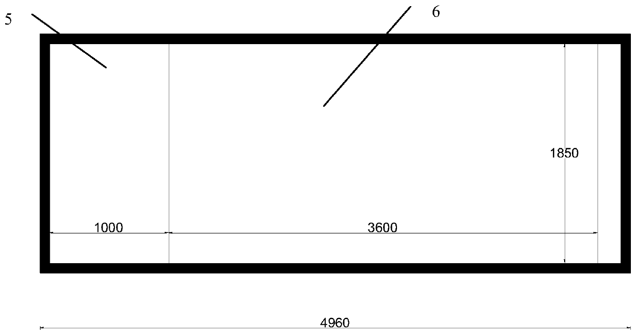
[0026] The bottom plate of the soil body box 1 is divided into two parts, a movable steel plate 5 and a fixed steel plate 6; the surroundings of the movable steel plate 5 are movable, and are softly connected with the surrounding side gaps with canvas to avoid the soil from falling during loading.

[0027] The actuator ...


PUM


Abstract

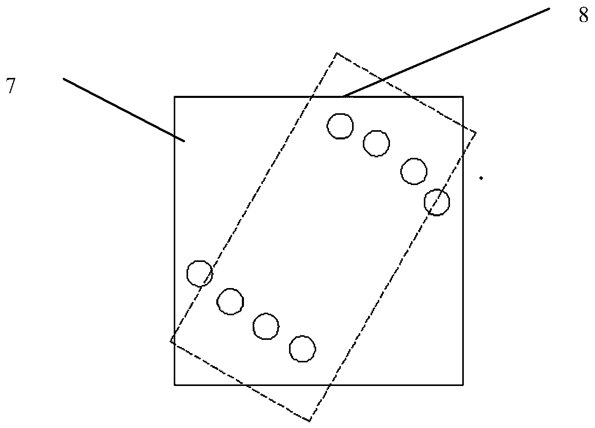
The invention discloses a test device for simulating the surface rupture deformation of a reverse fault under an earthquake. The test device comprises a soil box, a profile steel frame, limiting devices and an actuator; the soil box is fixed to the profile steel frame, and a bottom plate of the soil box is divided into a movable steel plate and a fixed steel plate; the periphery of the movable steel plate is movable. The top of the actuator is in contact with the middle part of the lower surface of the movable steel plate; the movable steel plate has the functions of bearing soil and pushing the soil under pushing of the actuator. The two sides of the movable steel plate are provided with the limiting devices respectively, and the limiting devices are used for restraining lifting of the movable steel plate by a certain angle and a trajectory when the movable steel plate is jacked by the actuator, so that lifting of the soil at the hanging wall of the reverse fault in the earthquake issimulated. The device has the advantages that errors are within a controllable range; the test phenomenon is obvious, the operability and the repeatability are high, experiment results are consistentwith those of existing research and practical experience, a basis can be provided for building avoidance and anti-fracture design and construction of a strong earthquake rupture zone, and the casualties and property losses are reduced.

Description

technical field [0001] The invention relates to the technical field of earthquake simulation tests, in particular to a test device for simulating surface rupture and deformation of reverse faults under earthquakes. Background technique [0002] The surface rupture effect of strong earthquakes is the phenomenon that the rupture zone propagates to the surface under the action of earthquake fault dislocation, and causes damage or even collapse to the surface and nearby building structures. The dislocation of the fault will cause the deformation of the overlying soil layer, and the deformation of the soil layer will definitely pose a threat to the stability of the foundation of the building (structure) built on it. The building needs to avoid or resist the fracture design. Therefore, it is of great engineering practical value and scientific significance to study the development of overlying soil rupture caused by fault dislocation and the failure mechanism of building foundation...

Claims


Application Information

Patent Timeline
IPC IPC(8): G01N3/00G01N33/24
CPCG01N3/00G01N33/24G01N2203/0032G01N2203/0067G01N2203/0075G01N2203/0676G01N2203/0682
Inventor 张建毅王强张治州王拓
Owner INST OF DISASTER PREVENTION
Learn More