Wire welding auxiliary tool

An auxiliary tooling and wire technology, applied in auxiliary devices, welding equipment, connections, etc., can solve problems such as the influence of welding quality, achieve stable and reliable operation, simplify the installation process, and improve the height.

Active Publication Date: 2019-11-05
BEIJING AEROSPACE TIMES OPTICAL ELECTRONICS TECH
View PDF7 Cites 1 Cited by
  • Summary
  • Abstract
  • Description
  • Claims
  • Application Information

AI Technical Summary

Problems solved by technology

[0006] Third, when the heat-sensitive device is fixed during soldering, one hand needs to hold the wire to connect with the tube leg, and the other hand holds the electric soldering iron, which belongs to the electric soldering iron. Although the flux is applied to the solder joint, it is very difficult to It is easy to immerse into the wire skin, which will affect the welding quality. It is a prohibited and restricted process

Method used


Image

  • Wire welding auxiliary tool
  • Wire welding auxiliary tool
  • Wire welding auxiliary tool

Examples


Embodiment Construction

[0030] Below in conjunction with accompanying drawing and specific embodiment the present invention is described in further detail:

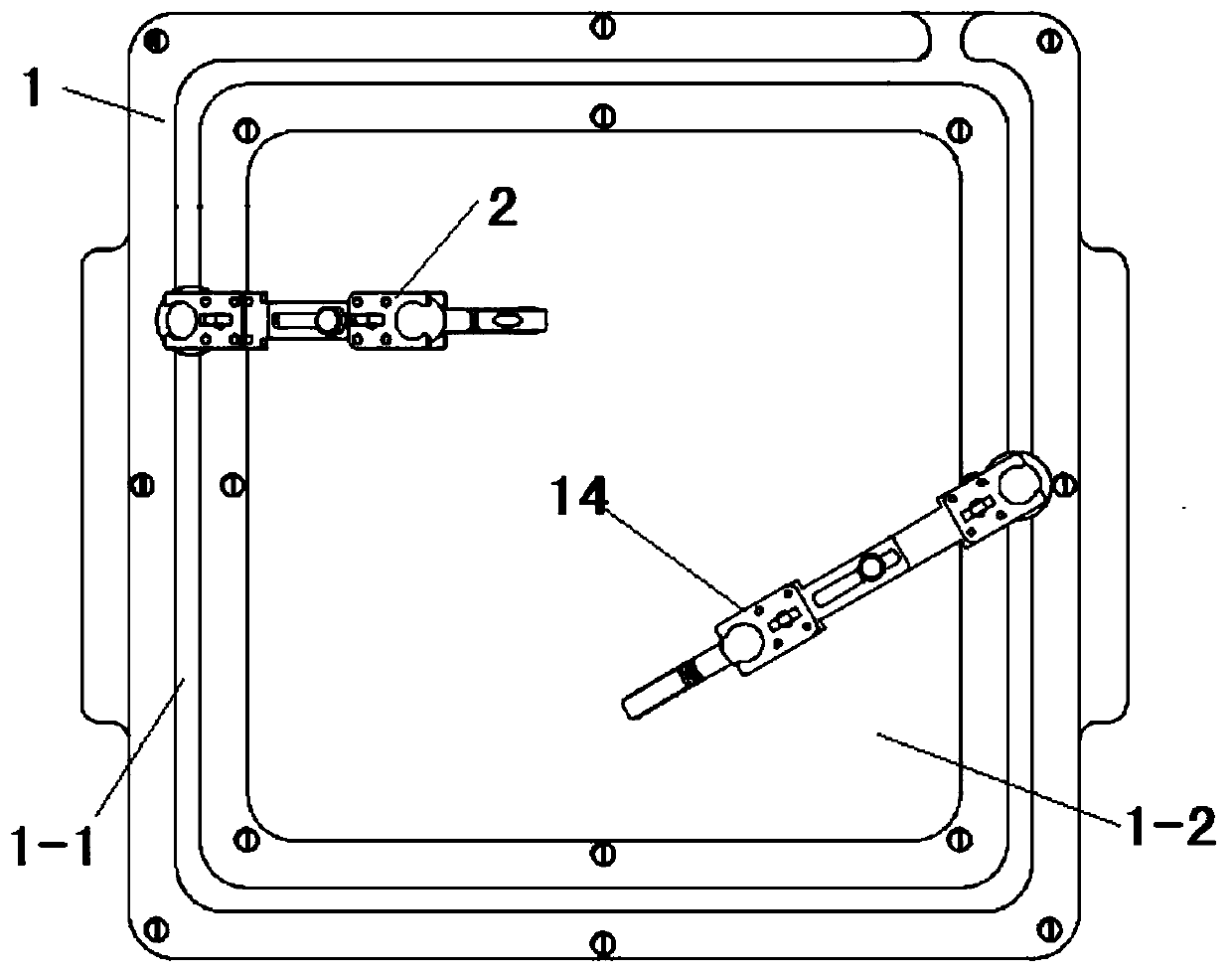
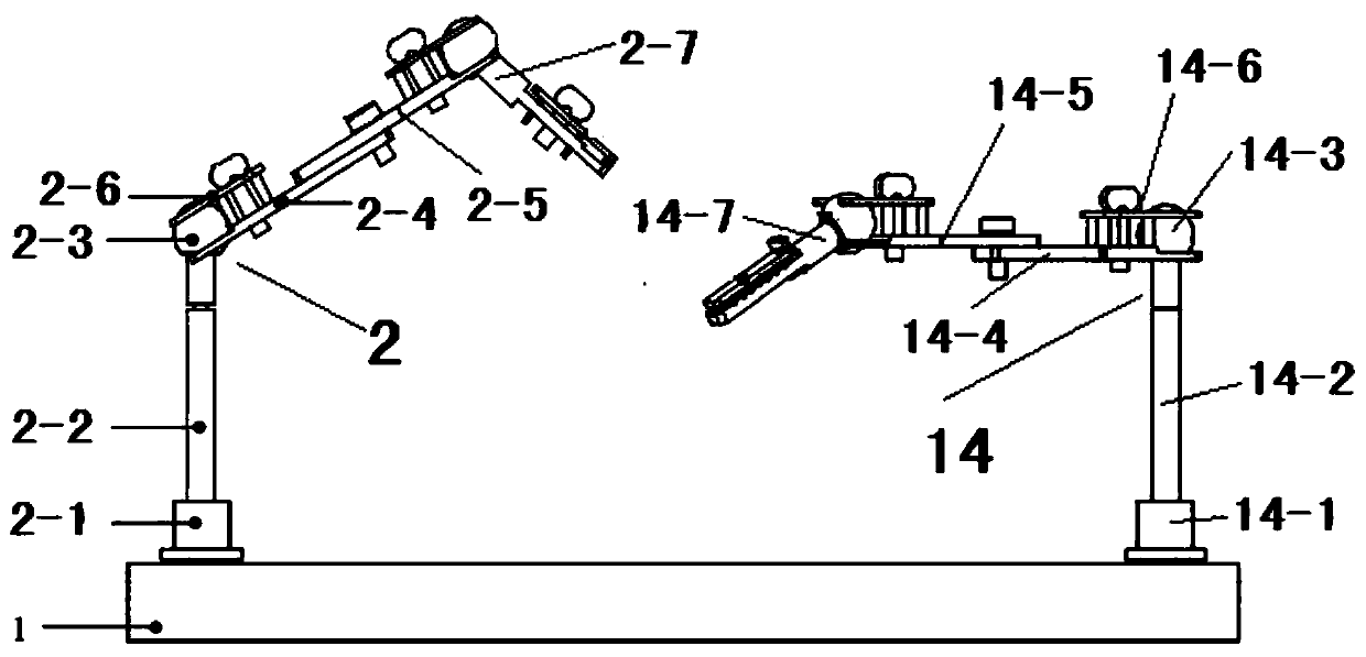
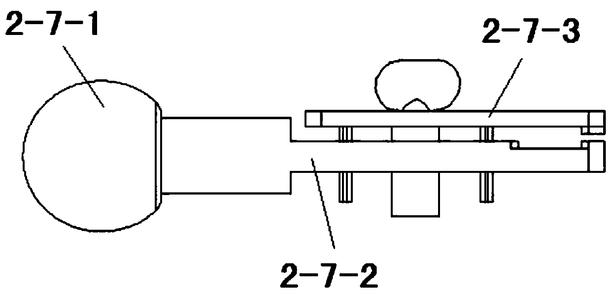
[0031] The invention provides a wire welding auxiliary tool, which is clamped by a base, a fastening screw sleeve, a support column, a universal ball connector, a connecting rod, a connecting rod pressing piece, a locking screw, a circuit board clamping device, and a wire clamping The cooperation of the device realizes the full contact between the wire and the solder hole of the circuit board or the tube leg of the device, and then takes the solder wire in one hand and the electric soldering iron in the other hand for one-time welding and forming. It makes up for the inconvenience of traditional electrical equipment, the need for secondary welding, black and non-wetting solder joints, and the use of prohibited and restricted processes.

[0032] Such as figure 1 Shown is a top view of the welding auxiliary tool. It can be seen from the figure th...


PUM


Abstract

The invention discloses a wire welding auxiliary tool, and relates to the technical field of circuit assembling tools. The wire welding auxiliary tool comprises a base, a circuit board fixing device and a wire fixing device, wherein the base is of a horizontally-placed rectangular plate-shaped structure, an annular groove rail is arranged on the upper surface of the base, the circuit board fixingdevice and the wire fixing device are arranged in the annular groove rail, the circuit board fixing device and the wire fixing device are used for realizing sliding positioning along the annular groove rail, anti-static foam is arranged on the upper surface of the base, the anti-static foam is of a rectangular plate-shaped structure, the anti-static foam is arranged in an annular ring of the annular groove rail, the circuit board fixing device is used for adjusting the posture and the position of an external to-be-welded circuit board, and the wire fixing device is used for adjusting the posture and the position of an external to-be-welded wire. According to the wire welding auxiliary tool, the effects that welding is carried out by holding soldering iron in one hand and holding a solder wire on the other hand, welding spot wetting effect is achieved, and the situation of load welding of electric soldering iron is caused in the traditional gyroscope electric assembling process is avoided are achieved.

Description

technical field [0001] The invention relates to the technical field of circuit assembly tooling, in particular to a wire welding auxiliary tooling. Background technique [0002] When the fiber optic gyroscope circuit board is replaced, it is usually operated with a structure. When the wire is soldered, the position of the circuit board is always difficult to flip due to structural reasons. The circuit board has no fixed position, and the wire needs to be penetrated into the through hole for welding. They are all hanging through. After welding, the solder joints of the wires are too high or the solder joints are black. The heat-sensitive device is being welded. First, the device is fixed, and the wire needs to be connected to the tube leg with one hand. Hold the device in one hand, let the tube leg connect to the solder joint of the wire, and use the iron in the other hand, which belongs to the electric soldering iron for soldering. Although the flux is applied to the solder ...

Claims


Application Information

Patent Timeline
Patent Type & Authority Applications(China)
IPC IPC(8): B23K3/08B23K3/00H01R43/02
CPCB23K3/00B23K3/08H01R43/02H01R43/0256
Inventor 蒋莉莉樊建琴殷利明许保祥陈亚刘笛胡永红
Owner BEIJING AEROSPACE TIMES OPTICAL ELECTRONICS TECH
Why Eureka
Try Eureka