A display device and a driving method thereof

A display device and a technology to be displayed, which are applied in static indicators, instruments, nonlinear optics, etc., can solve the problems of decreased light transmittance, poor transparent display effect, and poor transparency of devices, so as to improve light transmittance, Improve the transparent display effect and reduce the effect of occlusion

Active Publication Date: 2021-10-26
BOE TECH GRP CO LTD
View PDF6 Cites 0 Cited by
  • Summary
  • Abstract
  • Description
  • Claims
  • Application Information

AI Technical Summary

Problems solved by technology

For liquid crystal display devices, the basic principle of display is to use liquid crystals to modulate the polarization state of polarized light to achieve display, that is, to use upper and lower polarizers plus a liquid crystal cell structure, the liquid crystal changes the polarization state of light, so that part of the linearly polarized light can be emitted. Part of the linearly polarized light cannot be emitted; however, due to the setting of the polarizer, the transmittance of the light is significantly reduced, especially for transparent display devices, the polarizer on the surface of the panel will absorb a large amount of ambient light, making the transparency of the device extremely poor, making the liquid crystal display Device applications are greatly limited in the field of transparency
[0004] To sum up, the light transmittance of existing liquid crystal display products is low, and the transparent display effect is not good.

Method used


Image

  • A display device and a driving method thereof
  • A display device and a driving method thereof
  • A display device and a driving method thereof

Examples


Embodiment Construction

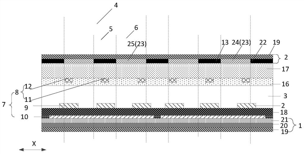
[0048] The embodiment of the present application provides a display device, such as figure 1As shown, the array substrate 1 and the opposite substrate 2 arranged oppositely, and the liquid crystal layer 3 between the array substrate 1 and the opposite substrate 2;

[0049] The display device is divided into a plurality of sub-pixel areas 4, and the sub-pixel area 4 is divided into a light-shielding area 5 and a light-transmitting area 6;

[0050] The sub-pixel area 4 includes an electrode structure 7, and the electrode structure 7 includes: a plurality of first electrodes 8 located between the opposite substrate 2 and the liquid crystal layer 3, located between the array substrate 1 and the A plurality of second electrodes 9 between the liquid crystal layers 3, and third electrodes 10 located between the array substrate 1 and the second electrodes 9; the first electrodes 8 are divided into first-type electrodes arranged alternately 11 and second type electrodes 12;

[0051] ...


PUM

PropertyMeasurementUnit
widthaaaaaaaaaa
widthaaaaaaaaaa
thicknessaaaaaaaaaa

Abstract

The application discloses a display device and a driving method thereof, which are used to improve the light transmittance of the display device. The display device includes: an array substrate, an opposite substrate, and a liquid crystal layer; the display device is divided into sub-pixel areas, and the sub-pixel areas are divided into light-shielding areas and light-transmitting areas; the sub-pixel areas include an electrode structure and a first light-shielding portion, and the electrode structure includes: The first electrode, the second electrode and the third electrode; the first electrode is divided into the first type electrode and the second type electrode; the electrode structure is configured as follows: the first type electrode, the second electrode and the third electrode apply the same voltage, and the first type electrode The first electrode and the second electrode apply different voltages to control the liquid crystal molecules to form a liquid crystal lens, so that the light passing through the liquid crystal lens converges to the first light-shielding part; it is also configured as follows: no voltage is applied to the first electrode, and the second electrode and the second electrode Different voltages are applied to the three electrodes to control the liquid crystal molecules to form a liquid crystal grating, so that at least part of the light passing through the liquid crystal grating is emitted from the light-transmitting region.

Description

technical field [0001] The present application relates to the field of display technology, in particular to a display device and a driving method thereof. Background technique [0002] With the increasing development of display technology, various display technologies are constantly emerging, among which, transparent display technology has attracted more and more attention because of the light transmission characteristics of the display panel. Since the transparent display device has a certain light penetration, it can not only display the picture on the display screen, but also watch the background behind the display screen through the display screen, so it is more suitable for building windows, car windows, shop windows, etc. . [0003] Liquid crystal display is a display device used on a large scale at present. It has a series of advantages such as high color gamut, lightness and thinness, and fast response time. It has mature technologies in theoretical research and pra...

Claims


Application Information

Patent Timeline
Patent Type & Authority Patents(China)
IPC IPC(8): G02F1/1343G02F1/1335G02F1/133G09G3/36
CPCG02F1/133G02F1/133512G02F1/134309G09G3/36G02F1/13624G02F1/292G09G3/3648G09G2300/0421G02F1/134381G02F1/294G02F1/136286G02F2201/307G09G3/3607G02F1/134345
Inventor 李忠孝张庆训赵文卿
Owner BOE TECH GRP CO LTD
Why Eureka
Try Eureka