Welding robot track automatic planning method
A welding robot and automatic planning technology, applied in the direction of manipulators, program control manipulators, manufacturing tools, etc., to achieve the effect of improving production efficiency and simple operation process
- Summary
- Abstract
- Description
- Claims
- Application Information
AI Technical Summary
Problems solved by technology
Method used
Image
Examples
Embodiment 1
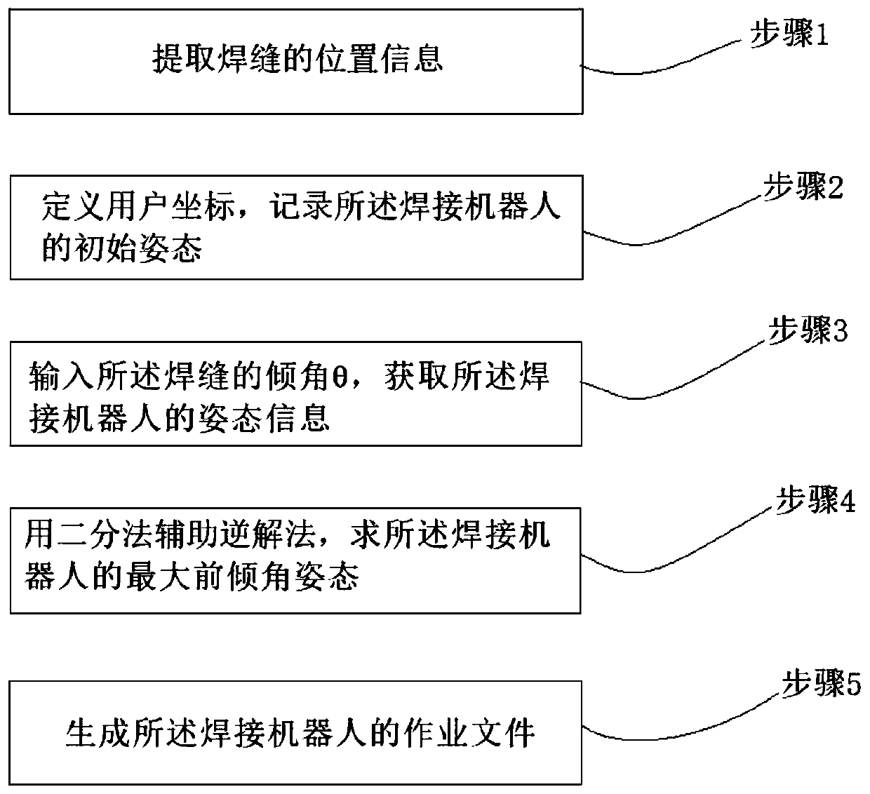
[0068] The principle of the automatic planning method for the trajectory of the welding robot disclosed in the present invention is as follows: figure 1 As shown, the attitude of the welding robot is solved in the form of vector, and the inverse solution method is assisted by the dichotomy to find the attitude of the robot with the maximum forward tilt angle.
[0069] exist figure 2 The working diagram of the welding robot shown includes a workpiece 1 , a welding seam 2 , a fixture 3 , a welding robot 4 , a tool coordinate system 5 and a user coordinate system 6 .
[0070] Wherein, the workpiece 1 is fixed by the clamp 3 , and the welding robot 4 aligns with the position of the welding seam 2 for welding.
[0071] Method provided by the invention comprises the following steps:
[0072] Step 1, extracting the position information of the weld 2;
[0073] Step 2, define the user coordinates, record the initial posture of the welding robot 4;
[0074] Step 3, input the inclin...
Embodiment 2
[0078] STEP is a common data format for CAD model data exchange between different design software. A weld 2 corresponds to a pentahedron in the CAD model, and the start and end points of the weld are found according to the topological relationship.
[0079] The part coordinate system can be redefined in SolidWorks software, which is convenient for user coordinate system teaching.
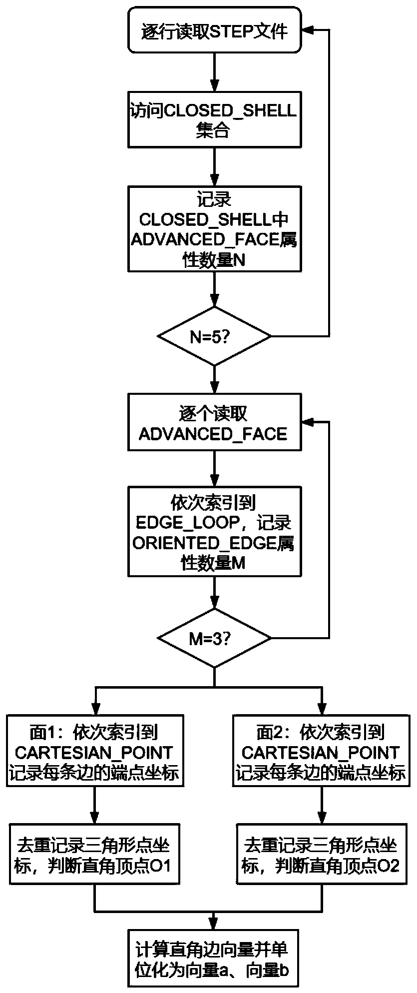
[0080] On the basis of embodiment one, step 1 is based on the STEP file, including the following sub-steps (such as image 3 shown):
[0081] Step 1.1, read the STEP file line by line, and judge whether it contains the "CLOSED_SHELL" field;
[0082] Step 1.2, visit the CLOSED_SHELL collection, record the number N of ADVANCED_FACE attributes in the CLOSED_SHELL collection;
[0083] Step 1.3, judging whether N is equal to 5; if N is equal to 5, enter the next step;
[0084] Step 1.4, read ADVANCED_FACE attributes one by one, index to EDGE_LOOP in turn, record the number M of ORIENTED_EDGE attribut...
Embodiment 3
[0092] On the basis of embodiment two, step 2 includes:
[0093] Step 2.1, teach three points on the part to determine the user coordinate system 6, the user coordinate system 6 coincides with the part coordinate system in the CAD model, and record the initial posture of the welding robot 4 under the user coordinate system (Rx t ,Ry t ,Rz t );
[0094] Step 2.2, according to (-sin(Ry t ),cos(Ry t )sin(Rx t ),cos(Rx t )cos(Ry t )) Calculate the initial posture of the welding robot 4, and record it as vector t based on the direction of the tool coordinate system z-axis vector 0 , vector t 0 is the vector of the initial posture of welding robot 4:
[0095] t 0 =(sin(Ry t ),-cos(Ry t )sin(Rx t ),-cos(Rx t )cos(Ry t ));
[0096]Step 2.3, remember the vector a 0 (0,0,1) is the transition vector, vector t 0 to vector a 0 The first rotation matrix of is obtained by Rodrigue's rotation formula; according to the first rotation matrix, the vector t is reversed 0 to ve...
PUM
 Abstract
Description
Claims
Application Information
 - R&D
- Intellectual Property
- Life Sciences
- Materials
- Tech Scout
- Unparalleled Data Quality
- Higher Quality Content
- 60% Fewer Hallucinations
Browse by: Latest US Patents, China's latest patents, Technical Efficacy Thesaurus, Application Domain, Technology Topic, Popular Technical Reports.
© 2025 PatSnap. All rights reserved.Legal|Privacy policy|Modern Slavery Act Transparency Statement|Sitemap|About US| Contact US: help@patsnap.com


