Flexible pushing mechanism for sealing rings

A pusher mechanism and sealing ring technology, which is applied in metal processing, metal processing equipment, manufacturing tools, etc., can solve the problems of increasing the work intensity of tooling management personnel, affecting product production efficiency, and poor error prevention effect, so as to shorten the zero replacement The effect of reducing mold time, reducing tooling and tooling management costs, and good concentricity

Pending Publication Date: 2019-10-25
BORGWARNER AUTOMOTIVE COMPONENTS (NINGBO) CO LTD
View PDF0 Cites 1 Cited by
  • Summary
  • Abstract
  • Description
  • Claims
  • Application Information

AI Technical Summary

Problems solved by technology

When using manual single picking operation, it is necessary to add photoelectric picking reminder and sensor error prevention to the program, because the shape of the open ring is prone to "knotting" phenomenon, and a single picking will be more than 2 or more sealing rings, and in the When it is put back again, it will cause the photoelectric pick-up induction alarm, which will cause employees to complain, and there will often be quality complaints such as overfilling or missing loading, and the error prevention effect is poor; The principle is to connect sealing rings, gaskets and circlips in series, and use a similar "bullet loading" structure design to realize single push feeding and detection and error prevention. Each time a material is pushed and there is a proximity switch for detection, The effect of error prevention is good, but it needs to switch different tooling during production, and a lot of adjustment time and tooling maintenance time are required when multiple sets of tooling are replaced at the same time, which will affect the production efficiency of the product and increase the work intensity of the tooling management personnel, which needs to be improved

Method used


Image

  • Flexible pushing mechanism for sealing rings
  • Flexible pushing mechanism for sealing rings
  • Flexible pushing mechanism for sealing rings

Examples


Embodiment Construction

[0032] In order to make the technical solutions and advantages of the present invention clearer, the present invention will be further described in detail below in conjunction with the accompanying drawings.

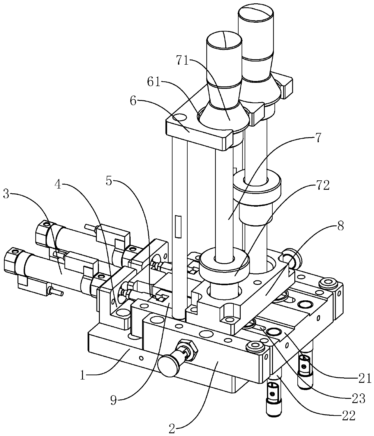
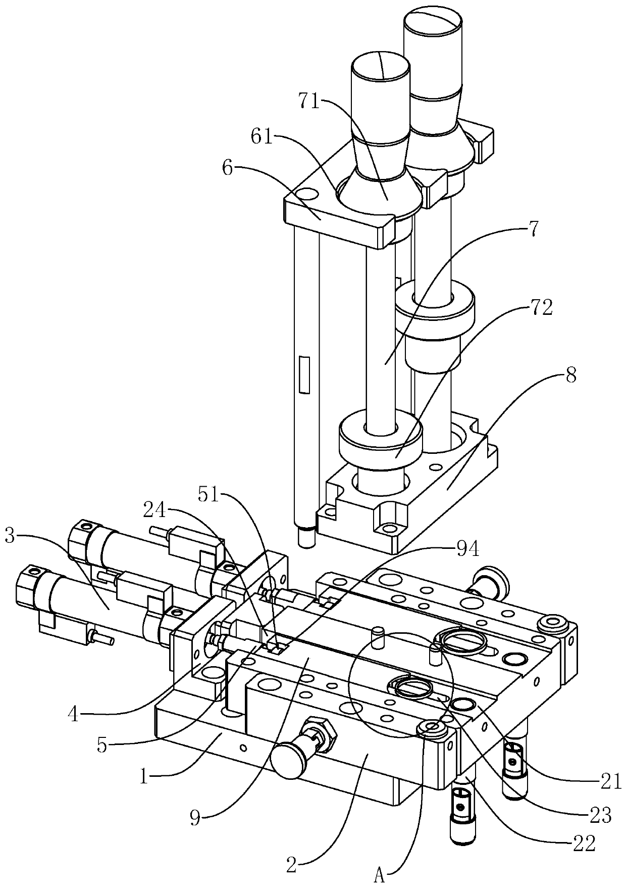
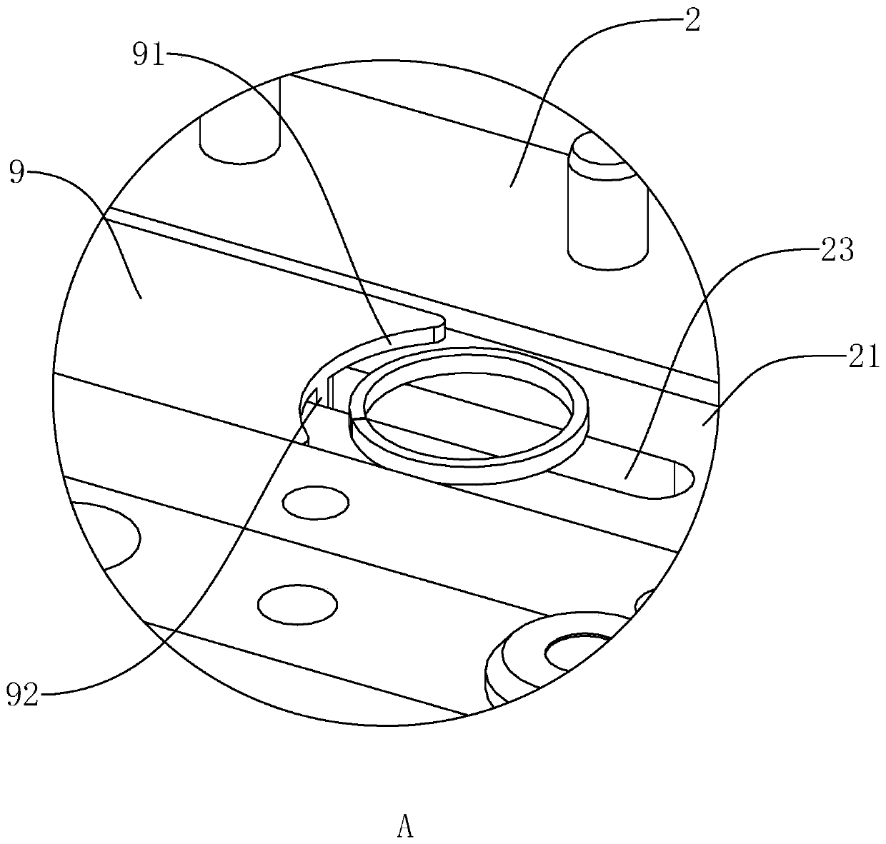
[0033] Such as figure 1 As shown, a sealing ring flexible pushing mechanism includes a fixed base 1 . A pushing seat 2 and a pushing cylinder 3 are arranged on the fixed base 1 . At the same time, a pushing block 9 for pushing the sealing ring is provided on the upper side of the pushing seat 2, and the pushing cylinder 3 is connected with the pushing block 9 and drives the pushing block 9 to reciprocate along the length direction of the pushing seat 2 and To achieve the role of pushing the sealing ring. The material storage support 6 is also arranged on the material pushing seat 2 . The material storage support 6 is provided with a material guide roller 7 for socketing a plurality of sealing rings, and the material guide roller 7 is inserted into the material storage...


PUM


Abstract

The invention discloses a flexible pushing mechanism for sealing rings. According to the technical scheme, the flexible pushing mechanism comprises a fixed base, a pushing base and a pushing cylinderare arranged on the fixed base, a pushing block is arranged on the upper side of the pushing base, the pushing cylinder is connected with the pushing block and drives the pushing block to do reciprocated motion in the length direction of the pushing base, the pushing base is provided with a storage bracket, the storage bracket is provided with a guiding roller which is inserted into the storage bracket in the vertical direction, and a gap matched with the corresponding sealing ring thickness is formed between the bottom of the guiding roller and the pushing base. By means of the flexible pushing mechanism, the pushing block is driven by the pushing cylinder to push the sealing rings in the gap to the end away from the pushing cylinder, the aim of pushing the sealing rings in different models, types and sizes can be achieved by replacing the corresponding guiding rollers, the product process error proofing capability and the production efficiency are significantly improved, the time ofzero mold replacing between most products with the sealing rings in different sizes is shortened, and the tool cost and the tool management cost are effectively reduced.

Description

technical field [0001] The invention relates to the technical field of turbocharger assembly equipment, more specifically, it relates to a sealing ring flexible pushing mechanism. Background technique [0002] The shafting structure of the core assembly of the turbocharger is complex in design, and there are many thin slices and ring-shaped parts, such as the scroll end seal ring, floating bearing, gasket and retaining ring, etc. Since the structure, quantity and size of different series are also different, it will be inconvenient to pick up due to the relatively small materials during production and assembly, and it is prone to the risk of missing and overpacking. In addition, in the field of commercial vehicle superchargers, there are many types of different series of products, and the production is carried out in a small batch mode, which seriously affects the process error-proofing ability and production efficiency of the product. [0003] In the prior art, we usually u...

Claims


Application Information

Patent Timeline
Patent Type & Authority Applications(China)
IPC IPC(8): B23P19/00
CPCB23P19/001
Inventor 冯模盛陈刚兰运涛毛晓峰
Owner BORGWARNER AUTOMOTIVE COMPONENTS (NINGBO) CO LTD
Why Eureka
Try Eureka