
Manufacturing method for conical box body structural member

A manufacturing method and a technology for structural parts, which are applied in the field of manufacturing conical box structural parts, can solve the problems of difficult welding deformation, many weld seams, and high precision requirements for conical box structural parts, and achieve convenient welding and reduced deformation Effect

Active Publication Date: 2019-10-25
WUHAN MARINE MACHINERY PLANT
View PDF6 Cites 6 Cited by
  • Summary
  • Abstract
  • Description
  • Claims
  • Application Information

AI Technical Summary

Problems solved by technology

[0003] In the process of realizing the present invention, the inventor found that the prior art has at least the following problems: since the upper cover plate is installed on the hull, the weight of the entire full-turn rudder and propeller device is borne by it, and the conical box and the rotary shaft exist Matching relationship, the accuracy requirements of the conical box structure are relatively high
However, there are more than 400 welds in the whole component, and the welds are many and large, so it is very difficult to control the welding deformation

Method used


Image

  • Manufacturing method for conical box body structural member
  • Manufacturing method for conical box body structural member
  • Manufacturing method for conical box body structural member

Examples


Embodiment Construction

[0052] In order to make the object, technical solution and advantages of the present invention clearer, the implementation manner of the present invention will be further described in detail below in conjunction with the accompanying drawings.

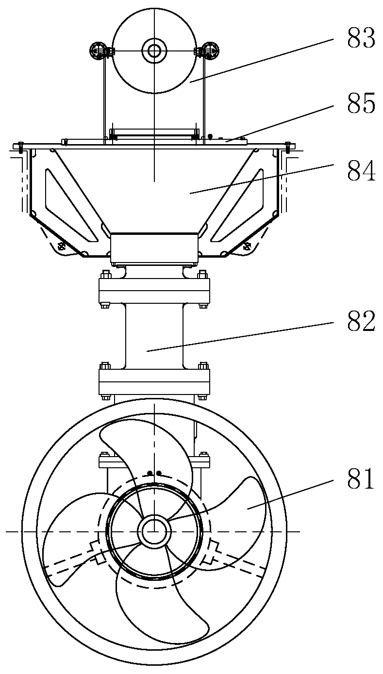
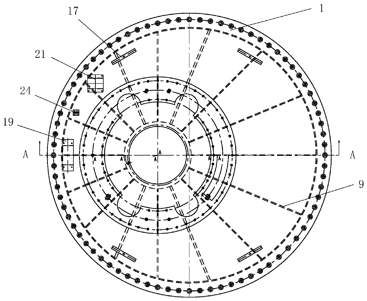
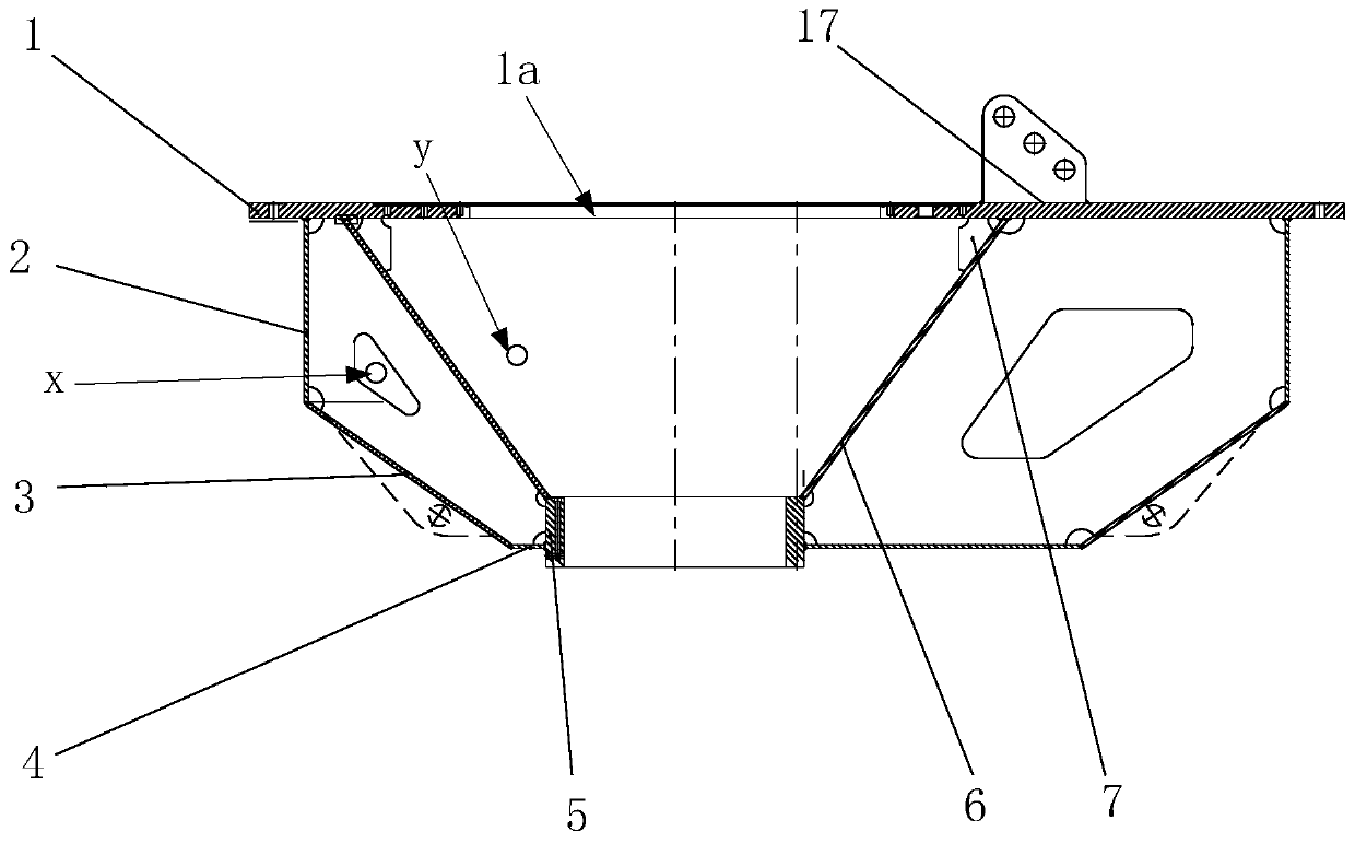
[0053] In order to facilitate the understanding of the technical solution provided by the embodiment of the present invention, the function and structure of the tapered box structure 84 will be introduced first. The conical box structure 84 is an important load-bearing member of the rotary unit 82, such as figure 1As shown, the upper part of the conical box structure 84 is connected to the brake assembly 83 , and the lower part is connected to the propulsion unit 81 . There is a close cooperation relationship between the tapered box and the rotary shaft of the rotary unit 82 , the rotary bearing (not shown in the figure) and the box cover 85 . The upper cover plate 1 of the conical box structure 84 is installed on the hull, and the we...


PUM


Abstract

The invention discloses a manufacturing method for a conical box body structural member, and belongs to the field of structural member manufacturing. The method comprises the following steps that an upper cover plate, a conical box body plate, a ring, a rib plate group, a side sealing plate, a lower bottom plate, a bottom sealing plate and a small rib plate are provided; the conical box body plate, the ring and the rib plate group are correspondingly assembled to the front surface of the upper cover plate; welding seams among the conical box body plate, the ring, and the upper cover plate arewelded; the side sealing plate and the lower bottom plate are correspondingly assembled to the front surface of the upper cover plate; a welding seam between the upper cover plate and the rib plate group, a welding seam between the conical box body plate an the rib plate group, a welding seam between the ring and the rib plate group, a welding seam between the upper cover plate and the side sealing plate, a welding seam between the rib plate group and the side sealing plate, a welding seam between the ring and the lower bottom plate and a welding seam between the rib plate group and the lowerbottom plate are welded correspondingly; the bottom sealing plate and the small rib plate are correspondingly assembled and welded to the front surface of the upper cover plate, a conical box body main body structure is obtained, the bottom sealing plate covers the rib plate set, the large end of the bottom sealing plate is connected with the side sealing plate, and the small end of the bottom sealing plate is connected with the circumferential wall of the lower bottom plate; and the conical box body main body structure is annealed to form the conical box body structural member.

Description

technical field [0001] The invention relates to the field of manufacturing structural parts, in particular to a method for manufacturing a tapered box structural part. Background technique [0002] The full-turn rudder-propeller device includes a sequentially connected propulsion unit (such as a propeller), a slewing unit and a brake assembly. The slewing unit includes a slewing shaft, a slewing bearing, and a tapered box structure for installing the slewing shaft and the slewing bearing. The tapered box structure includes an upper cover plate and inner and outer two-layer plates arranged on one side of the upper cover plate. The inner plate is a cone cylinder, the upper end of the outer plate is a straight cylinder, and the lower end is a cone cylinder. There are criss-cross ribs between the two layers of plates to strengthen and connect. [0003] In the process of realizing the present invention, the inventor found that the prior art has at least the following problems:...

Claims


Application Information

Patent Timeline
IPC IPC(8): B23K31/02B23P15/00
CPCB23K31/02B23P15/00
Inventor 代俊王法斌李焕明
Owner WUHAN MARINE MACHINERY PLANT
Learn More