
Loudspeaker sound cavity drainage structure for accelerating drainage by utilizing repeated audio frequency

A drainage structure and sound cavity technology, applied in the field of communication, can solve problems such as poor experience, blocked audio output, borrowing tools, etc., to achieve the effect of improving user experience, restoring normal use, and shortening the time of blockage

Pending Publication Date: 2019-10-22
SHENZHEN 3G ELECTRONICS CO LTD
View PDF0 Cites 2 Cited by
  • Summary
  • Abstract
  • Description
  • Claims
  • Application Information

AI Technical Summary

Problems solved by technology

[0002] With the development of technology and the special use environment of some customers, waterproof products have become the standard configuration of electronic products such as smart wearable devices and mobile phones. However, when users accidentally soak in water when using waterproof products, the water will enter the speaker along with the sound guide groove. In the sound cavity, although it will not enter the interior of the electronic product, if it is not discharged in time, it will block the audio output and affect the quality of the call
[0003] However, when water or liquid enters the sound cavity of the speaker in the current market, because the inner wall of the sound cavity is flat, the accumulated water is not easy to throw out, and then it can be dried by a hair dryer or evaporated naturally to restore normal use. This method restores slowly and requires borrowing tools. poor experience

Method used


Image

  • Loudspeaker sound cavity drainage structure for accelerating drainage by utilizing repeated audio frequency
  • Loudspeaker sound cavity drainage structure for accelerating drainage by utilizing repeated audio frequency
  • Loudspeaker sound cavity drainage structure for accelerating drainage by utilizing repeated audio frequency

Examples


Embodiment 1

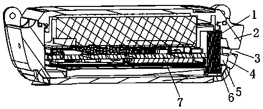
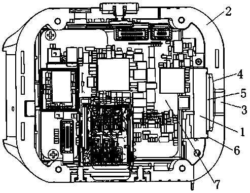
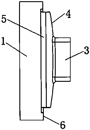
[0022] see Figure 1-3 , in an embodiment of the present invention, a horn sound cavity drainage structure that utilizes heavy audio to accelerate drainage includes a horn 1, a housing 2, a sound outlet 3, a sound cavity 5, and a main board 7, and the main board 7 and the horn 1 are installed Fixed in the casing 2 , a sound chamber 5 is fixedly arranged on the outside of the speaker 1 , and the sound chamber 5 is connected to the sound outlet hole 3 opened on the casing 2 .

[0023] The sound cavity 5 has a structure protruding in an arc shape from the middle to the outside. The inner end of the sound cavity 5 is sealed and connected with the horn 1, and the outer end of the sound cavity 5 is sealed and connected with the sound hole 3, which is convenient for straight or flat products (depending on Sound hole 3 design direction) After the liquid is collected and discharged.

Embodiment 2

[0025] see Figure 1-3 The difference between this embodiment and Embodiment 1 is that further, the speaker 1 is sealed and fixedly connected with the housing 2 and the sound cavity 5 through the waterproof foam 6, so as to avoid the water body from causing damage to the main board 7 and other components. influence, improve the sealing of the connection.

[0026] Further, the sound outlet hole 3 is circular, or other shapes, and the sound outlet hole 3 is connected to the middle of the outer end of the sound cavity 5 .

[0027] Further, the main board 7 is used to provide a subwoofer audio, and after the speaker 1 plays, the diaphragm pushes the airflow to discharge the liquid in the sound chamber 5 from the sound outlet 3 .

[0028] Further, the sound cavity 5 is provided with an inner wall arc 4 whose four outer ends are inclined toward the central axis of the sound hole 3, and the outer ends of the four inner wall arcs 4 are connected to the sound hole 3, that is, the soun...


PUM


Abstract

The invention relates to the field of communication, in parituclar to a loudspeaker sound cavity drainage structure for accelerating drainage by utilizing the repeated audio frequency, which comprisesa loudspeaker, a shell, a sound outlet hole, a sound cavity and a main board; the main board and the loudspeaker are both installed and fixed in the shell, the sound cavity is fixedly arranged on theouter side of the loudspeaker, the sound cavity is of a structure with the middle protruding outwards in an arc shape, and the sound cavity is connected with the sound outlet hole formed in the shell. The main board is used for providing a mega bass audio which is played by the loudspeaker, and then the diaphragm pushes the air flow to discharge the liquid in the sound cavity from the sound outlet hole. When the product is soaked in water, water entering the sound cavity of the loudspeaker is not easy to discharge, and the call quality is influenced, besides natural drainage, the loudspeakercan be used for playing audio to push airflow to assist drainage, the time that the sound cavity of the loudspeaker is blocked by liquid such as water is shortened, normal use of the product is rapidly recovered, and the user experience is improved.

Description

technical field [0001] The invention relates to the communication field, in particular to a loudspeaker cavity drainage structure which utilizes heavy audio to accelerate drainage. Background technique [0002] With the development of technology and the special use environment of some customers, waterproof products have become the standard configuration of electronic products such as smart wearable devices and mobile phones. However, when users accidentally soak in water when using waterproof products, the water will enter the speaker along with the sound guide groove. Although the sound cavity will not enter the interior of the electronic product, if it is not discharged in time, it will block the audio output and affect the quality of the call. [0003] However, when water or liquid enters the sound cavity of the speaker in the current market, because the inner wall of the sound cavity is flat, the accumulated water is not easy to throw out, and then it can be dried by a h...

Claims


Application Information

Patent Timeline
IPC IPC(8): H04R9/06H04R9/02
CPCH04R9/02H04R9/06H04R2400/11
Inventor 黄有军饶良定
Owner SHENZHEN 3G ELECTRONICS CO LTD
Learn More