
Array camera adjusting device and adjusting method

A technology for array cameras and adjustment devices, which is applied in the direction of cameras, camera bodies, supporting machines, etc., and can solve problems such as the inability to adjust the positional relationship between cameras and cameras in array cameras, long cycle times, and long cycle times for processing brackets, etc.

Active Publication Date: 2019-10-22
MEGVII BEIJINGTECH CO LTD
View PDF5 Cites 13 Cited by
  • Summary
  • Abstract
  • Description
  • Claims
  • Application Information

AI Technical Summary

Problems solved by technology

[0003] At present, the algorithm development of the array camera depends on the relative positional relationship between the cameras, but the array camera is often assembled into a finished product and then debugged and verified. This often takes a long time, for example, the production cycle is usually more than 1 month, and it is flexible. Poor performance, because once the finished array camera is manufactured, it is generally impossible to adjust the positional relationship between the camera and the camera in the array camera, and there are the following two problems:
[0004] First, the relative position between the cameras in the array camera is usually fixed by brackets and glue, but the cycle of making and processing the bracket is often longer, and the time to assemble the array camera is longer, which seriously affects the evolution speed of the array camera algorithm
[0005] Second, in the development stage, the relative positional relationship between the cameras in the array camera should not be fixed, but needs to be adjusted continuously according to the test results. Therefore, it is difficult for the cameras with relatively fixed positions to meet the needs of equipment flexibility in the development stage. requirements, resulting in low test efficiency of the array camera, seriously affecting the development process of the array camera

Method used


Image

  • Array camera adjusting device and adjusting method
  • Array camera adjusting device and adjusting method
  • Array camera adjusting device and adjusting method

Examples


Embodiment Construction

[0102] Embodiments of the present application are described in detail below, examples of which are shown in the drawings, wherein the same or similar reference numerals denote the same or similar elements or elements having the same or similar functions throughout. The embodiments described below by referring to the figures are exemplary only for explaining the present application, and are not construed as limiting the present application.

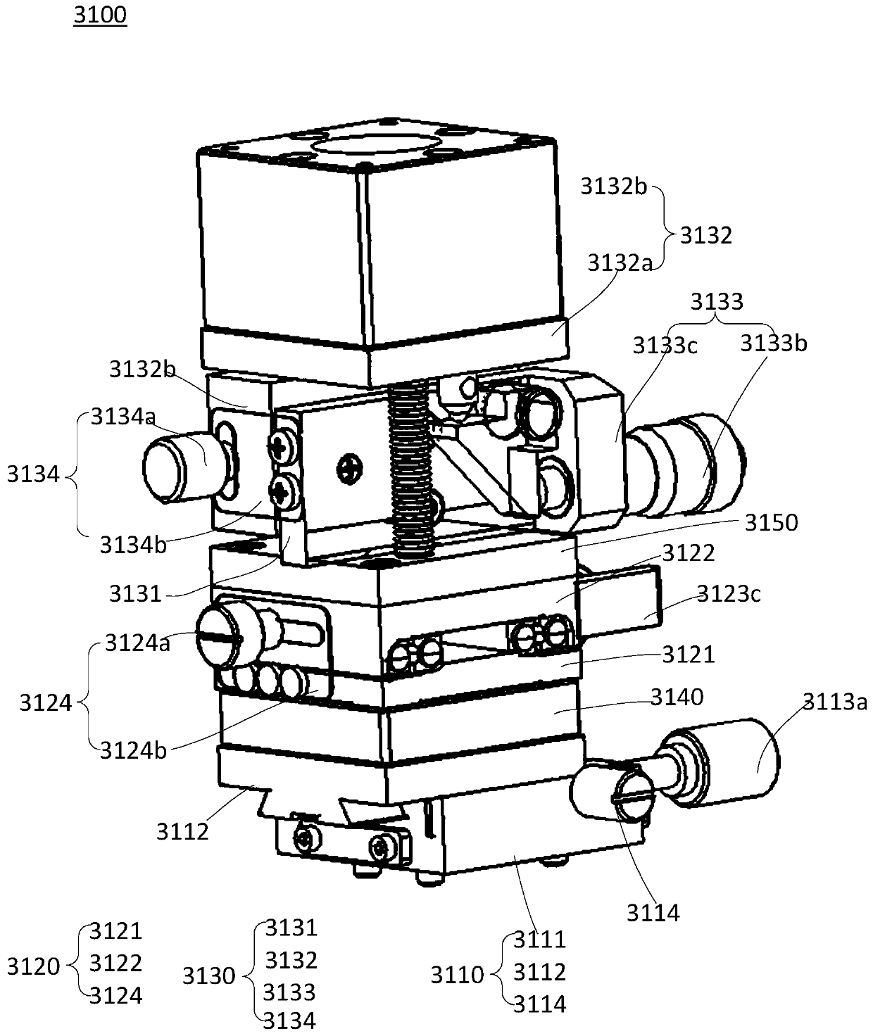
[0103] The first aspect of the present application provides an array camera adjustment device, such as figure 1 As shown, it includes a bracket 1000 , and a translation module 2000 , a detection module 4000 , at least one adjustment module 3000 and at least one camera fixing module 5000 arranged on the platform 1100 of the bracket 1000 . The adjustment module 3000 is set on the movable translation module 2000 . The camera fixing module 5000 is arranged on the adjusting module 3000, and the camera fixing module 5000 is used to fix the arra...


PUM


Abstract

The invention provides an array camera adjusting device and an array camera adjusting method. The array camera adjusting device comprises a support, a translation module, a detection module, at leastone adjustment module and at least one camera fixing module, wherein the translation module, the detection module, the at least one adjustment module and the at least one camera fixing module are arranged on a platform of the support; the adjustment modules are movably arranged on the translation module; the camera fixing modules are arranged on the adjustment modules, and the camera fixing modules are used for fixing an array camera; and the adjustment modules are used for adjusting and fixing the spatial position and / or the spatial angle of each camera in the array camera. According to the array camera adjusting device, the translation module, the detection module and the adjustment modules are arranged, the spatial position and the spatial angle of each camera on the array camera can beflexibly adjusted, so that the assembling time of the array camera in the development process of the array camera is greatly shortened, the flexibility requirement of the array camera development equipment is met, the development efficiency of the array camera is improved, and the development cost is saved.

Description

technical field [0001] The present application relates to the technical field of photography equipment, and in particular, to an array camera adjustment device and adjustment method. Background technique [0002] Array camera is to replace the shooting effect of one large camera with multiple small cameras, which is similar to the compound eyes of array astronomical telescopes and insects. Compared with traditional cameras, array cameras have a wider field of view, larger photos, and smaller equipment. To make use of the above characteristics, it needs to rely on the combination of software and hardware of the array camera. [0003] At present, the algorithm development of the array camera depends on the relative positional relationship between the cameras, but the array camera is often assembled into a finished product and then debugged and verified. This often takes a long time, for example, the production cycle is usually more than 1 month, and it is flexible. Poor perf...

Claims


Application Information

Patent Timeline
IPC IPC(8): F16M11/04F16M11/12F16M11/18G03B17/56
CPCF16M11/045F16M11/046F16M11/048F16M11/12F16M11/18G03B17/561
Inventor 梁钢
Owner MEGVII BEIJINGTECH CO LTD
Learn More