
A screw-insert method for assembling large-size shaft-hole workpieces

A large-size, workpiece technology, applied in the field of assembly of large-size shaft hole workpieces

Active Publication Date: 2020-11-10
TSINGHUA UNIV
View PDF7 Cites 0 Cited by
  • Summary
  • Abstract
  • Description
  • Claims
  • Application Information

AI Technical Summary

Problems solved by technology

On the basis of the existing active and compliant assembly method, the present invention makes it easier for the mechanical arm to avoid mechanical jamming during the assembly process of large-size shaft hole workpieces. The operation method is simple and easy, and the assembly efficiency and assembly success can be effectively improved. Rate

Method used

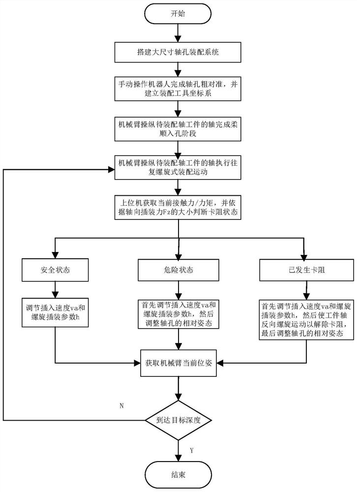

Image

  • A screw-insert method for assembling large-size shaft-hole workpieces
  • A screw-insert method for assembling large-size shaft-hole workpieces
  • A screw-insert method for assembling large-size shaft-hole workpieces

Examples


Embodiment Construction

[0044] The present invention proposes a screw-inserting method for assembling large-size shaft-hole workpieces. The present invention will be further described in detail below in conjunction with the accompanying drawings and specific embodiments. The following examples serve to illustrate the present invention, but do not limit the scope of the present invention.

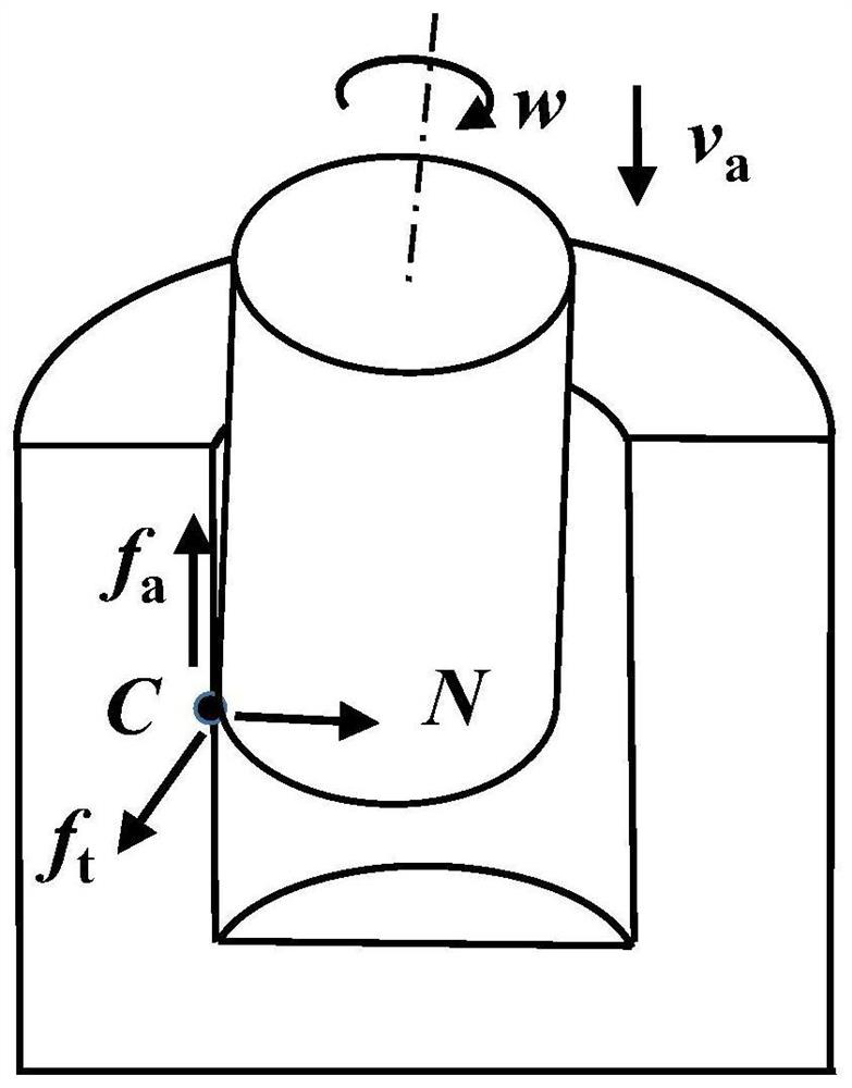
[0045] The present invention proposes a spiral insertion method for assembling workpieces with large shaft holes, which reduces axial frictional resistance by constructing relative spiral motion between shaft holes, figure 1 The basic principle of reducing the axial friction force in the assembly process in the method of the present invention is given: in the process of screw insertion, the workpiece shaft is at an axial linear velocity v a And the angular velocity w around the axis is in contact with the workpiece hole at point C, the spiral motion changes the friction resistance between the shaft holes, that is, ...


PUM


Abstract

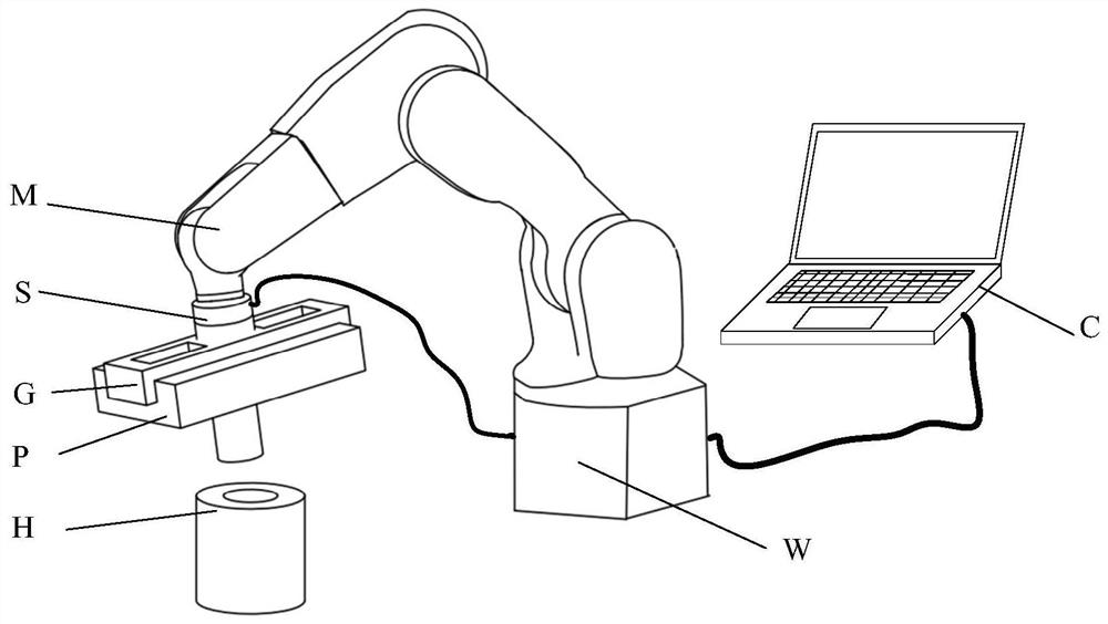
A screw insertion method for large-size peg-in-hole workpiece assembly. During implementation, a mechanical arm (M) receives a movement instruction of an upper computer (C), and manipulates a large-size workpiece peg (P) so as to be inserted into a large-size workpiece hole (H) in the form of reciprocating screw movement; a force sensor (S) monitors, in real time, the contact force / moment between the peg and the hole; and the upper computer (C) uses the pose of the end of the mechanical arm (M) during assembly and the contact force / moment between the peg and the hole, to implement the function of adjusting the relative pose between the peg and the hole. Furthermore, the present invention is used to monitor the jamming state of peg-in-hole assembly, and adjust movement parameters of screw insertion, so as to reduce the frictional resistance between large-size peg-in-hole workpieces, and prevent mechanical jamming.

Description

technical field [0001] The invention relates to the field of assembling large-size shaft-hole workpieces, in particular to a screw-inserting method for assembling large-size shaft-hole workpieces. Background technique [0002] Assembly operation is one of the most important links in the manufacturing process, which directly determines the final quality of the product, and shaft hole assembly is the most common and important form of cooperation in assembly operations. At present, most of the assembly links in the industrial field are still completed by manual operation or semi-automatic tooling. With the development of automation technology, it has become a trend to use robots to realize automatic assembly operations. [0003] The mechanical jamming problem in the shaft hole assembly process is the main reason for the failure of robot automated shaft hole assembly. The gap between the shaft holes varies from a few millimeters to a few microns according to the process require...

Claims


Application Information

Patent Timeline
Patent Type & Authority Patents(China)
IPC IPC(8): B23P19/04B23P19/00
CPCB23P19/00B23P19/04
Inventor 徐静刘志陈恳吴丹王国磊
Owner TSINGHUA UNIV
Learn More