
Display panel, manufacturing method and display device

A technology for display panels and manufacturing methods, applied in nonlinear optics, instruments, optics, etc., can solve problems such as poor cost, thickened display device viewing angle compensation effect, etc., to achieve reduced box thickness, good viewing angle compensation effect, and orientation effect Good results

Inactive Publication Date: 2019-10-18
KUSN INFOVISION OPTOELECTRONICS
View PDF5 Cites 3 Cited by
  • Summary
  • Abstract
  • Description
  • Claims
  • Application Information

AI Technical Summary

Problems solved by technology

[0004] In order to overcome the shortcomings and deficiencies existing in the prior art, the object of the present invention is to provide a display panel, a manufacturing method and a display device, so as to solve the problem of thickening of the display device and poor viewing angle compensation effect in the prior art due to the attachment of a compensation film. and cost increases

Method used


Image

  • Display panel, manufacturing method and display device
  • Display panel, manufacturing method and display device
  • Display panel, manufacturing method and display device

Examples


Embodiment Construction

[0025] In order to further explain the technical means and effects of the present invention to achieve the intended purpose of the invention, the specific implementation, structure, The features and their functions are detailed as follows:

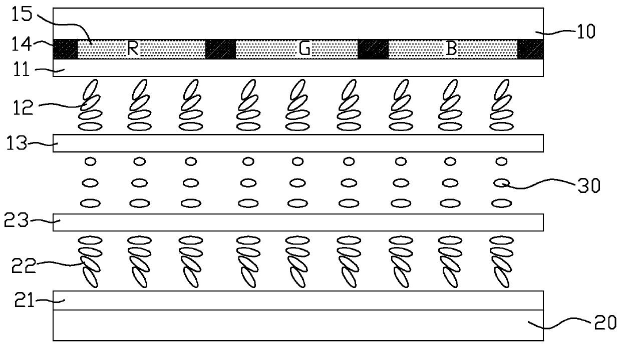
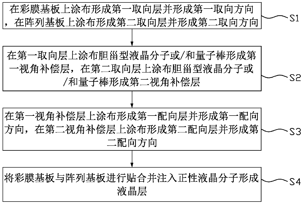
[0026] figure 1 is a schematic structural diagram of a display panel in an embodiment of the present invention, figure 2 is a flow chart of a method for manufacturing a display panel in an embodiment of the present invention, Figures 3a-3c It is a structural schematic diagram of the manufacturing process of the color filter substrate of the display panel in an embodiment of the present invention, Figures 4a-4c It is a structural schematic diagram of the manufacturing process of the array substrate of the display panel in an embodiment of the present invention.

[0027] Such as figure 1 As shown, the display panel provided by the present invention includes a color filter substrate 10, an array substrate 20 disposed opposite to the co...


PUM


Abstract

The invention discloses a display panel. The display panel comprises a color film substrate, an array substrate opposite to the color film substrate and a liquid crystal layer located between the color film substrate and the array substrate, wherein a first alignment layer is arranged on the color film substrate; a second alignment layer is arranged on the array substrate; the first alignment direction of the first alignment layer is perpendicular to the second alignment direction of the second alignment layer; positive liquid crystal molecules in the liquid crystal layer are in a twisted arrangement state from bottom to top at the beginning; the color film substrate is also provided with a first orientation layer and a first visual angle compensation layer; the first orientation layer isused for orienting the first visual angle compensation layer, and the first orientation direction of the first orientation layer is reversely parallel to the first alignment direction of the first alignment layer; the array substrate is further provided with a second orientation layer and a second visual angle compensation layer, the second orientation layer is used for orienting the second visualangle compensation layer, and the second orientation direction of the second orientation layer is reversely parallel to the second alignment direction of the second alignment layer. The invention discloses a manufacturing method and a display device.

Description

technical field [0001] The invention relates to the technical field of liquid crystal display, in particular to a display panel, a manufacturing method and a display device. Background technique [0002] A TN type (ECB type or OCB type, etc.) liquid crystal display device has a very narrow viewing angle (about 40°) due to its own liquid crystal arrangement. In order to compensate for the viewing angle, the most common method at present is to coat (Coating) a layer of discotic liquid crystal molecules (DLC) on the polarizer by FujiFilm Company of Japan. By aligning the orientation of the DLC with the liquid crystal molecules in the liquid crystal cell (Liquid crystal, LC for short) are anti-parallel in orientation, thereby widening the viewing angle (from about 40° to about 80°). Or, by attaching a viewing angle compensation film, that is, using a wide viewing angle compensation film for compensation (mainly using a polymer material with negative birefringence such as discot...

Claims


Application Information

Patent Timeline
Patent Type & Authority Applications(China)
IPC IPC(8): G02F1/1337
CPCG02F1/1337
Inventor 李宁杨永芳
Owner KUSN INFOVISION OPTOELECTRONICS
Learn More