
Robot clamping tool

A technology for clamping tooling and robots, which is applied in the field of robots, can solve problems such as inability to effectively adapt to workpieces with different diameters, unstable clamping, and damage to workpieces, so as to achieve uniform force, improve stress concentration, and protect workpieces.

Inactive Publication Date: 2019-10-18
CHONGQING UNIV OF ARTS & SCI
View PDF0 Cites 9 Cited by
  • Summary
  • Abstract
  • Description
  • Claims
  • Application Information

AI Technical Summary

Problems solved by technology

[0002] The special clamping tool is matched with the main machine or the production line to complete auxiliary work, such as grabbing the workpiece, loading and unloading, etc. This type of clamping tool serves the main machine and is driven by the main machine. Their working procedures are generally fixed. At present, the commonly used clamping tools include scissors, suction cups and other structures. For the scissors structure, for cylindrical workpieces, the clamping is unstable and cannot effectively adapt to workpieces with different diameters. The applicability is poor, and the suction cup The formula cannot be effectively applied to the arc outer surface of this type of workpiece; and for the same batch of workpieces, there are errors between the outer contours of each workpiece due to the influence of manufacturing accuracy, and the swing range of the fixture of this type of clamping tool is usually fixed. When the workpiece is due to When the outer contour of the manufacturing error becomes larger, the force of the fixture clamping on the workpiece will be greater, especially for fragile workpieces, if the clamping force is too large, the workpiece will be easily damaged;

Method used


Image

  • Robot clamping tool
  • Robot clamping tool
  • Robot clamping tool

Examples


Embodiment Construction

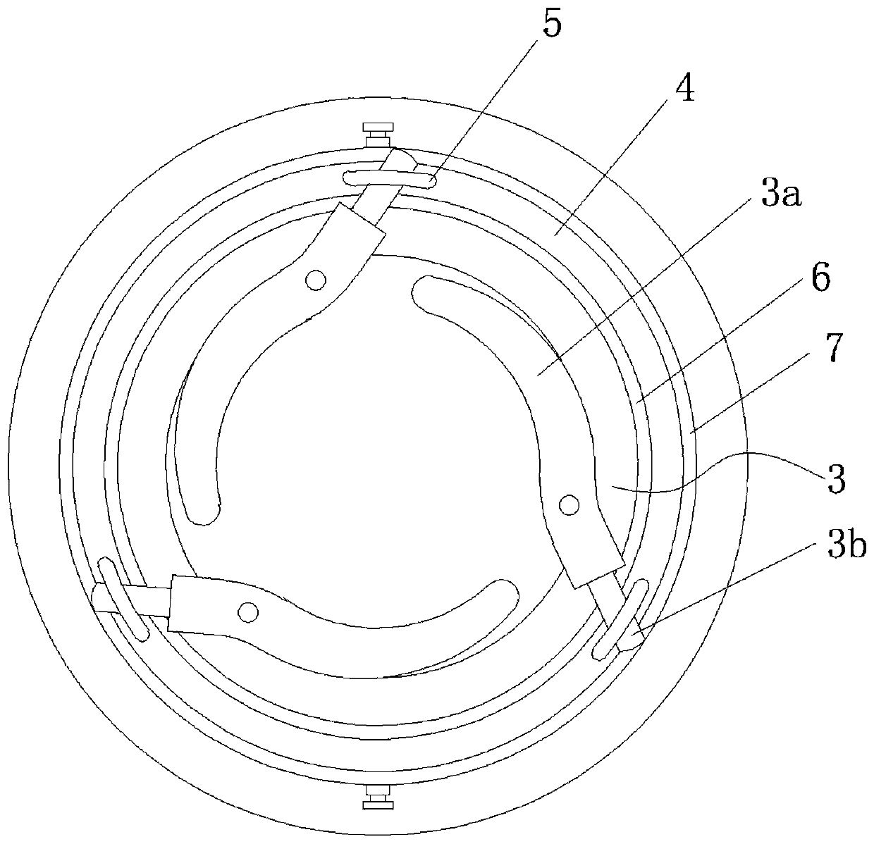
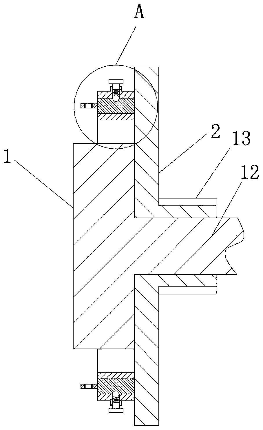
[0022] figure 1 It is a schematic diagram of the overall structure of the present invention; figure 2 It is a schematic diagram of the cooperation structure of the drive disk and the base disk of the present invention; image 3 for figure 2 The radial cross-sectional structural schematic diagram of ; Figure 4 for image 3 Schematic diagram of the enlarged structure at point A;

[0023] As shown in the figure: the clamping tooling of the robot in this embodiment includes a base plate 1, a drive plate 2 that rotates with the base plate, and several clamping arms arranged on the base plate symmetrically with the center axis of the base plate as the central axis. 3 and the unloading ring 4 arranged on the driving disk, the unloading ring and the driving disk are arranged coaxially, the clamping arm driver 5 corresponding to each clamping arm is connected on the described unloading ring 4, and the clamping arm There is a driving hole 5a on the driving part 5, the middle par...


PUM


Abstract

The invention discloses a robot clamping tool. The robot clamping tool comprises a base disc, a drive disc cooperating with the base disc in a rotation mode, a plurality of clamping arms arranged on the base disc and an unloading ring arranged on the drive disc, wherein the unloading ring drives clamp arms to swing and form an opening or clamping state, a dynamic locking mechanism is arranged on the drive disc and applies locking force to the unloading ring, the unloading ring and the drive disc cooperate in a transmission mode when relative torque of the unloading ring to the drive disc is smaller than locking torque of the dynamic locking mechanism, and the unloading ring overcomes the locking force and rotates relatively to the drive disc when the relative torque of the unloading ring to the drive disc is larger than the locking torque of the dynamic locking mechanism. The robot clamping tool has a clamping force unloading function, can automatically unload clamping force, and prevents the problem that the clamping force is large and damages a workpiece. The robot clamping tool drives the plurality of the clamp arms to synchronously rotate through rotation of the drive disc, anddue to the simple drive structure, the structure of the robot clamping tool is greatly simplified, and then the clamping arms are unified in motion, and synchronously clamp the workpiece, and therefore stress on the outer circle of the workpiece is uniform.

Description

technical field [0001] The invention belongs to the technical field of robots, and relates to a robot clamping tool. Background technique [0002] The special clamping tool is matched with the main machine or the production line to complete auxiliary work, such as grabbing the workpiece, loading and unloading, etc. This type of clamping tool serves the main machine and is driven by the main machine. Their working procedures are generally fixed. At present, the commonly used clamping tools include scissors, suction cups and other structures. For the scissors structure, for cylindrical workpieces, the clamping is unstable and cannot effectively adapt to workpieces with different diameters. The applicability is poor, and the suction cup The formula cannot be effectively applied to the arc outer surface of this type of workpiece; and for the same batch of workpieces, due to the influence of manufacturing accuracy, there are errors between the outer contours of each workpiece, an...

Claims


Application Information

Patent Timeline
IPC IPC(8): B25J15/00B25J15/10
CPCB25J15/00B25J15/10
Inventor 胡旭陈庆
Owner CHONGQING UNIV OF ARTS & SCI
Learn More