Tool clamp for screen mesh measuring sensor and using method

A technology for measuring sensors and fixtures, applied in the field of fixtures, can solve the problems of errors, waste of manpower, slippage of wires and solder joints, etc., to achieve high accuracy and avoid false welding.

Active Publication Date: 2019-10-18
SHANGHAI JIAO TONG UNIV
View PDF8 Cites 4 Cited by
  • Summary
  • Abstract
  • Description
  • Claims
  • Application Information

AI Technical Summary

Problems solved by technology

The above positioning method has the following disadvantages: it requires the cooperation of multiple people, which wastes manpower; it is difficult to accurately control the distance between the wire mesh, resulting in errors; the metal wire to be welded does not necessarily fit the surface of the circuit board pad, resulting in errors; the solder joints are not completely solidified when you let go , the cancellation of the pre-tightening force in the wire may cause slippage between the wire and the solder joint, resulting in false welding

Method used


Image

  • Tool clamp for screen mesh measuring sensor and using method
  • Tool clamp for screen mesh measuring sensor and using method
  • Tool clamp for screen mesh measuring sensor and using method

Examples


Embodiment Construction

[0034] The following describes the preferred embodiments of the present invention with reference to the accompanying drawings to make the technical content clearer and easier to understand. The present invention can be embodied in many different forms of embodiments, and the protection scope of the present invention is not limited to the embodiments mentioned herein.

[0035] In the drawings, components with the same structure are denoted by the same numerals, and components with similar structures or functions are denoted by similar numerals. The size and thickness of each component shown in the drawings are shown arbitrarily, and the present invention does not limit the size and thickness of each component. In order to make the illustration clearer, the thickness of parts is appropriately exaggerated in some places in the drawings.

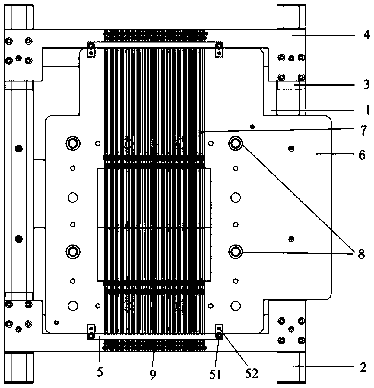
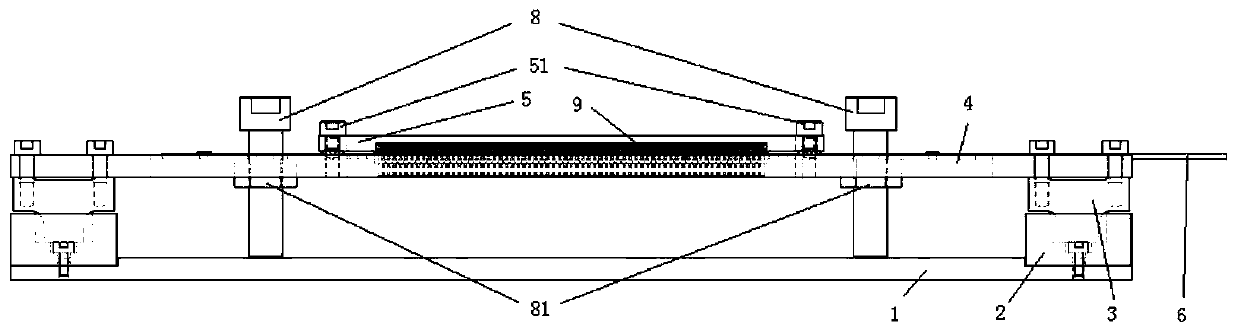
[0036] Such as figure 1 Shown is an embodiment of a tooling fixture for a wire mesh measuring sensor of the present invention, including a bo...


PUM


Abstract

The invention discloses a tool clamp for a screen mesh measuring sensor. The tool clamp comprises a bottom plate, two clamping plates, clamping plate fixing devices, two positioning strips and tightening bolts; clamping grooves which are adjustable in depth and are the same as a circuit board of the screen mesh measuring sensor in thickness are formed in the surfaces of the clamping plates; the clamping plate fixing devices are used for fixedly connecting the clamping plates and the bottom plate, the two clamping plates are fixed in parallel, and the directions of the clamping grooves are opposite; the two positioning strips of sawtooth-shaped grooves are arranged at the positions in contact with to-be-welded metal wires of the screen mesh measuring sensor, and the distance between the adjacent sawtooth centers is the metal wire array to-be-controlled distance; and the tightening bolts are located on the clamping plates, used for tensioning the metal wires, used for determining the metal wire positions and used for adjusting the metal wire tightening force. The invention also discloses a using method based on the tool clamp. The tool clamp is simple and practical, the positions ofthe metal wires on a circuit board can be positioned with high accuracy, the pretightening force of the metal wire and the distance between the metal wire and a bonding pad can be adjusted, false welding and virtual welding are avoided, meanwhile, pre-winding and primary welding can be carried out, and manpower and welding time can be greatly saved.

Description

technical field [0001] The invention relates to the field of tooling fixtures, in particular to a tooling fixture for wire mesh measuring sensors and a use method. Background technique [0002] Fixtures refer to devices used to clamp workpieces (or guide tools). [0003] During the welding process of the conductive wire mesh sensor, the spacing of the metal wire array of the wire mesh sensor is precisely controlled, so that the wire is completely attached to the surface of the circuit board pad, and a pre-tightening force is applied to it at the same time. Existing welding is to adopt traditional manual positioning of wire. The above positioning method has the following disadvantages: many people are required to cooperate, which wastes manpower; it is difficult to accurately control the distance between the wire mesh, resulting in errors; the metal wire to be welded does not necessarily fit the surface of the circuit board pad, resulting in errors; the solder joints are not...

Claims


Application Information

Patent Timeline
Patent Type & Authority Applications(China)
IPC IPC(8): B23K3/08
CPCB23K3/08
Inventor 熊进标王颖龙李涛曲文海
Owner SHANGHAI JIAO TONG UNIV
Why Eureka
Try Eureka