
Emergency rescue platform for tunnel

An emergency rescue and tunnel technology, applied in the field of tunnel rescue, can solve problems such as inconvenience of movement, tunnel collapse, and inconvenient functional rescue of the injured, so as to reduce space occupation and facilitate use.

Pending Publication Date: 2019-10-11
朱豫江
View PDF0 Cites 4 Cited by
  • Summary
  • Abstract
  • Description
  • Claims
  • Application Information

AI Technical Summary

Problems solved by technology

[0007] The purpose of the present invention is to provide a kind of emergency rescue platform for tunnels to solve the above-mentioned background technology. The location of the injured is not easy to move, which makes it inconvenient to rescue the injured's body. It takes up a lot of space inside the tunnel, and it is inconvenient to store the platform. There is insufficient use. The platform cannot support the inner wall of the tunnel, and it is easy to appear in the tunnel. Partial landslides, causing safety hazards for the injured and rescuers

Method used


Image

  • Emergency rescue platform for tunnel
  • Emergency rescue platform for tunnel
  • Emergency rescue platform for tunnel

Examples


Embodiment 1

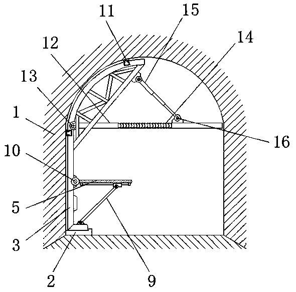
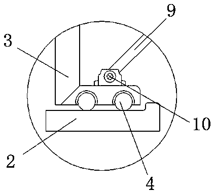
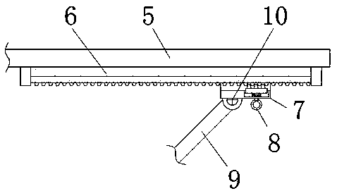
[0024] An emergency rescue platform for a tunnel, including a tunnel body 1, a guide pillow 2, a bracket 3, a ball 4, a rescue plate 5, a sliding rod 6, a sliding sleeve 7, a positioning member 8, a support rod 9, a first rotating shaft support 10, Slide rail 11, telescopic rod 12, second rotating shaft support 13, connecting spring 14, hydraulic rod 15, third rotating shaft support 16 and protective net 17, guide pillow 2 is fixedly installed at the bottom corner of tunnel body 1, And the bottom end of the support 3 is provided on the guide pillow 2, and a ball 4 is installed between the bottom of the support 3 and the guide pillow 2, and the inner side of the middle part of the support 3 is connected with a rescue board 5, and the bottom of the rescue board 5 is provided with a slide bar 6, and the sliding rod 6 is connected with a sliding sleeve 7, and the bottom of the sliding sleeve 7 is provided with a positioning member 8, and a supporting rod 9 is connected between the ...

Embodiment 2

[0025] Embodiment 2: The side section of the guide pillow 2 is set as an "L"-shaped structure, and the bottom of the guide pillow 2 and the bracket 3 are engaged with each other, and the bracket 3 is slidingly connected to the top of the guide pillow 2 through the ball 4 , the rescue board 5 and the bracket 3 constitute a relative overturn structure, and the connection end of the rescue board 5 and the bracket 3 and the connection end of the bracket 3 and the support rod 9 are relatively dislocated in the vertical plane, and the outer wall of the bracket 3 is in contact with the tunnel body 1 The inner walls are attached to each other.

[0026] The difference between this embodiment and Embodiment 1 is that the position of the bracket 3 is convenient to move, so that the bracket 3 can be guided when it is moved so that the rescue board 5 can be folded and stored when it is turned over, reducing the space occupied. At the same time, the structure of the bracket 3 is set , can s...

Embodiment 3

[0027] Embodiment 3: The sliding sleeve 7 and the sliding rod 6 form an engaged sliding connection, and the sliding sleeve 7 and the positioning member 8 form a relative lifting structure, and the top of the positioning member 8 and the bottom of the sliding rod 6 are both arranged in a strip shape The zigzag structure, the telescopic rod 12 is set to a shape with thick middle part and thin at both ends, and the maximum telescopic length of the telescopic rod 12 is greater than the maximum distance between the inner walls of the tunnel body 1, and the tunnel body 1 and the bracket 3 are rotatably connected, and the bracket 3 forms a triangular structure with the telescopic rod 12 and the hydraulic rod 15.

[0028] The difference between this embodiment and Embodiment 1 is that the turning angle of the rescue board 5 and the bracket 3 is changed by sliding the sliding sleeve 7 and the sliding rod 6, so as to facilitate the use and storage of the rescue board 5, and the structura...


PUM


Abstract

The invention discloses an emergency rescue platform for a tunnel. The emergency rescue platform comprises a tunnel body, a slide rail, a telescopic rod and a hydraulic rod. Guide pillows are fixedlymounted at the bottom corners of the tunnel body, one end of the bottom of a bracket is arranged on each guide pillow, a rescue plate is connected to the inner side of the middle portion of the bracket, a slide bar is arranged at the bottom of the rescue plate, a support rod is connected between a sliding sleeve and the bottom of the bracket, the connecting position of the support rod, the slidingsleeve and the bracket and the connecting position of the bracket and the rescue plate are fixedly provided with first rotating shaft supports, the sliding rail is mounted on the inner wall of the tunnel body, the connecting position of the telescopic rod and the bracket is provided with a second rotating shaft support, and the outer wall of the telescopic rod is connected to the top of the bracket through the hydraulic rod. By means of the emergency rescue platform for the tunnel, folding and storing of the platform can be carried out, use is facilitated, space occupation is reduced, transfer of injured persons can be effectively carried out, and the inner wall of the tunnel is supported for preventing collapse.

Description

technical field [0001] The invention relates to the technical field of tunnel rescue, in particular to an emergency rescue platform for tunnels. Background technique [0002] The emergency rescue platform for tunnels is the equipment for construction rescue operations when an emergency occurs inside the tunnel. Through the use of the rescue platform, it is convenient for the timely rescue of the injured and avoids the damage of the physical functions of the injured due to untimely rescue. Physical health problems affecting the injured person. [0003] However, the existing emergency rescue platform for tunnels has the following problems for users: [0004] 1. The position of the platform is inconvenient to move. When injuries occur in different areas, the rescue of the injured is likely to be delayed and the position of the injured is not easy to move, resulting in inconvenience in the rescue of the injured's body functions; [0005] 2. The platform occupies a large space ...

Claims


Application Information

Patent Timeline
Patent Type & Authority Applications(China)
IPC IPC(8): E21F11/00E21F17/00E21D19/00
CPCE21D19/00E21F11/00E21F17/00
Inventor 朱豫江陈江萍李程
Owner 朱豫江
Learn More