Eureka AIR delivers breakthrough ideas for toughest innovation challenges, trusted by R&D personnel around the world.

A kind of blocking conveying vehicle equipment used on the railway track of the mine

A technology for conveying cars and rails, applied in railway car body parts, transportation and packaging, automatic brakes, etc., can solve problems such as safety accidents, economic losses, and complex structure of the upper car stop, to prevent accidents and increase safety. Effect

Active Publication Date: 2020-04-07
全椒县同力标准件制造有限公司
View PDF6 Cites 0 Cited by
  • Summary
  • Abstract
  • Description
  • Claims
  • Application Information

AI Technical Summary

Problems solved by technology

[0002] When the mine car is transported underground, it relies on the rails laid in the roadway. The mine car often needs to be parked on the rail to load or unload coal. Because the rails are inclined in the road section, the mine car will slip due to gravity and its own inertia. It affects the safety of coal transportation, so it is necessary to install a car stop device on the track or vehicle. The upper car stop device of the traditional vehicle has a complicated structure and high maintenance cost. It is not economical to apply it to the conveyor car in the coal mine. active operation
When the personnel do not operate properly or forget to operate, the phenomenon of vehicle slipping will occur, resulting in economic losses and safety accidents.

Method used


Image

  • A kind of blocking conveying vehicle equipment used on the railway track of the mine
  • A kind of blocking conveying vehicle equipment used on the railway track of the mine
  • A kind of blocking conveying vehicle equipment used on the railway track of the mine

Examples


Embodiment Construction

[0019] Combine below Figure 1-Figure 5 The present invention is described in detail, for the convenience of description, the orientations mentioned below are now specified as follows: figure 1 The projection relationship of itself is the same as the up, down, left, right, front, and rear directions.

[0020] The invention relates to a device for blocking and conveying vehicles on the rails of a mine road, which is mainly used in the process of forgetting to turn on the stopper or the secondary slip of the mine-way conveying vehicle. Further explanation:

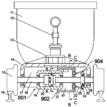
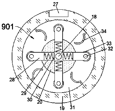
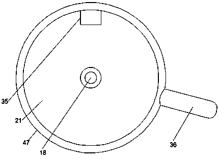
[0021] According to the present invention, a blocking conveying vehicle equipment used on a mine railroad track comprises a loading frame 11 and a connecting box 14 fixedly arranged at the lower end of the loading frame 11. The connecting box 14 is provided with a transmission cavity 17 with a downward opening. The transmission cavity 17 is rotatably connected with a transmission shaft 18 passing through the transmission c...


PUM


Abstract

The invention discloses conveying vehicle stopping equipment used on a mine tunnel rail. The conveying vehicle stopping equipment used on the mine tunnel rail comprises a loading frame and a connecting box fixedly arranged at the lower end of the loading frame; and a transmission cavity with a downward opening is formed in the connecting box. According to the conveying vehicle stopping equipment used on the mine tunnel rail, by using a foot brake structure arranged on a wheel axle and a one-way shaft coupling structure connected with the foot brake structure, the synchronous rotation shaft coupling direction is arranged on an obliquely downward side; during the rolling of a wheel, the one-way shaft coupling structure starts the foot brake structure to limit the rotation of the wheel axle;and moreover, by using a mechanism with a centrifugal rotating disc, the foot brake structure part is pulled to guarantee that the foot brake part cannot interfere the movement of a vehicle no matterhow the advancing direction of the vehicle is changed in the case of normal moving; the equipment can be independently arranged on the wheel axle and automatically recognizes, judges and stops the vehicle without being manually started so that accidents are effectively prevented; and moreover, the conveying vehicle stopping equipment used on the mine tunnel rail can work together with an existingvehicle stopper to realize double vehicle stopping protection so that the safety of mine tunnel operation is enhanced.

Description

technical field [0001] The invention relates to the technical field of rail mine cars, in particular to a blocking conveying vehicle device used on a rail of a mine. Background technique [0002] When the mine car is transported underground, it relies on the rails laid in the roadway. The mine car often needs to stop on the rail to load or unload coal. Since the rail is inclined in the road section, the mine car will slip due to gravity and its own inertia. It affects the safety of coal transportation, so it is necessary to install car blocking equipment on the rails or vehicles. The upper car blocking device of traditional vehicles has a complex structure and high maintenance cost. It is not economical to apply it to the conveyor vehicle in the coal mine. Active operation. When the personnel do not operate in place or forget to operate, the phenomenon of slippage will occur, resulting in economic losses and safety accidents. The invention clarifies a device that can autom...

Claims


Application Information

Patent Timeline
Patent Type & Authority Patents(China)
IPC IPC(8): B61H11/04
CPCB61H11/04
Inventor 童娟英
Owner 全椒县同力标准件制造有限公司
Why Eureka
Eureka Blog
Learn More